Cover fills are the long, long, long-awaited ability of model polygons (slabs, roofs, meshes, zones) to display fills in plan.


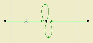
A roof and nothing but a roof.

This going to mean a lot less drawing over things to show fills and to get elements to hide one another.

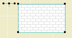
Cover fills have all of the features of regular fills, including background pen, local origin, and rotation. Roofs can automatically rotate the fill pattern to align with the roof slope. You can set the cover fill to be the same as the vectorial hatching on the 3D material.

Display of cover fills is controlled by a new display option.


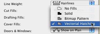
Selecting 'No Fills' puts the model polygons the way they were in AC8.1.

Notice that there are now a total of three fill display options. Further, 'Polygon Fills' has become 'Drafting Fills' and 'Construction Fills' has become 'Cut Fills'.

The distinction between Cover, Cut, and Drafting fills is called the Fill Category. You need to be aware of this because you can actually draft a cut or cover fill, which will display according to the relevant display option.

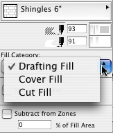
In Options -> Fill Types, you can limit the categories a fill can be used for. For example, shingles can't be used for cut fills.

Since you can set the category in the fill settings, and not all fills can be used for every category, you may find in a certain case that some fills are "missing". If so, check that the fill category in the settings is "drafting".


Fill Category in Info Box

AC9 brings the ability to save views with different dimension settings. The most prominent example would be the desire to dimension plans with feet & fractional inches, and site plans with decimal feet. Now you don't have to switch dimension settings back and forth, or explode dimensions, or other such tedium.

To make it easier to maintain the dimension settings, we use the long-standing, little-noticed Dimension Standards.


"Standards" in Dimension Preferences

There are two standards which we use in our views. "Site" is used for site plans. "Plan" is used for everything else. You could also set a standard for details if you wanted to display smaller fractions.

The view sets in the templates are configured to use the appropriate standard. For running projects, you will have to redefine your site plan views. Set the "Site" standard in the dimension settings, then redefine the view. (It's just like changing the scale or the layers.) Your plans should be OK, but it never hurts to check.

So now, views save scale, layers, display options, zoom, and dimension standard.

The GDL implementation in AC9 adds the option for the object designer to make edges detectable in plan for the purpose of selection.


Detecting Cutline JAM9

This ability can be added to any line or arc. I'm working it into the libraries gradually, going for maximum convenience and minimum nuisance. In addition the cutline above, all the JAM9 trim tools are detectable by the front edge. This should make easier to select trims, which tend to coincide a lot. I am listening for suggestions.

Look closely at the image above and you will see that the special snap points (midpoint, etc.) show up on these edges.

Remember that this is only for detection. There's no polyline editing ability. You can use such edges for splitting and adjusting, but not Cmd+clicking. (Yes, I reported that.)

Text editing in AC9 is completely overhauled, one of the few features that is.


Different.

The changes to the text tool are too great for me to cover here. Generally, it is more like editing in Word. All of the typical variations in text are available, and the shortcuts for bold (Cmd+B), etc., work as they should. You can mix any text effects within a single text element. Cmd+A works to select all the text when editing a block. Text can be stretched and expanded. Text can be copied and pasted from Word, with complex formatting preserved.

Text blocks can also have an outline box, and a background color, and you can control the offset of the text to the block edge.

It's a lot of stuff. If they had styles they would be done.

You should look over the section in the manual about the new Text, which starts on page 306, and/or the section in the New Features Guide, page 74.

Here's a couple of minor improvements to the polygon and polyline editing palettes.

At a polygon edge, there is one new button that always appears, and another that appears in a particular situation.


Polygon Edge Palette

The third button turns an edge into a curve, using a tangent instead a point on the curve.

The fifth button turns a chamfered corner into a pointed corner. It will only appear when you click on an edge between two other edges that would converge at a point outside the polygon. Example: turning an octagon into a square.

If you select a polyline and click on the end node, you get a palette with the third button shown here.


Add to polyline

If you click on this button, you can add nodes to the polyline. Good feature, half-implemented: You can only add straight segments. Sigh.

In AC9, the pet palettes for the arrow tool transformation functions and the element-specific editing functions have been combined. This is awesome.

Here's the Mesh palette:


In past versions, there was one palette which came up under the arrow tool, which had the dragging, mirroring, etc. buttons. Then for each tool there was a different palette which had the buttons for moving a node, curving an edge, filleting, etc. Now, regardless of whether you have the the arrow tool on, an expanded palette appears which has all the buttons of both groups.

This smoothes out the whole editing process because there's a lot less switching to the arrow tool and back.

They also improved the transformation (rotate, etc.) functions of the palette. Now you might actually use them. If you select rotate or mirror, you can select the base point for the transformation, like with the regular command. In 8.1, these palette functions would take as the base point the point where the palette came up, making them IMHO useless.