
Location: 06 Wood & Plastic / Structure
An object for modeling and annotating wood structure elements.
Placement:
The object is placed by the top. If sloped, it is placed by the top of the top end. If "Model" is off, there will be no 3D; use this to place a note only.
Composition:
Quantity, Stock, Header plywood. The quantity is unlimited, although you can only graphically edit up to five. (If you have a five-piece wood beam, you should be looking at steel.) The stock offers the typical assortment of dimension lumber, TJIs, and LVLs. The stock can be custom, in which case you can enter the beam depth, width, and label text. The header option adds plywood between the members to fit in a stud wall.
Geometry:
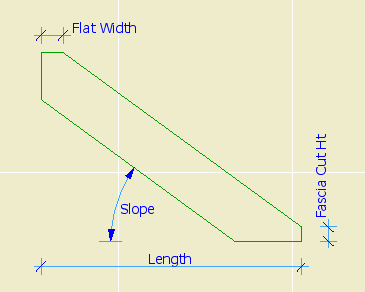
The beam can be level or sloped. The slope can be roof slope and/or angle in degrees. You can control the cut angle at each end (Vertical, Horizontal, Perpendicular, Custom). If the top angle is vertical, you can set a "flat" width to saw off the top point. If the bottom angle is vertical, you can set a fascia cut height.
3D slope editing
The length is top plane of the beam. Note that for some angle conditions (e.g., horizontal or perpendicular), the actual length may be longer than the length in the settings. If the actual length at the top is greater than the settings length, you can choose to show the actual extent by turning on "Show top extent".
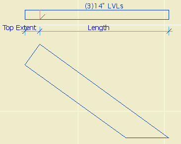
Top extent
The beam can be laid flat. I don't offer an arbitrary roll angle at this time.
Plan:
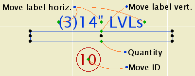
Show the true width or a broken line. The centerline is detectable. A text label can be shown, see below. Move the label side to side with the 3 spots in line with the text. Move the label up (less common) with the spot centered under the text. Modify the quantity with the spot in the middle of the beam across from the text.
Plan editing
The ID tag is optional. If the ID is empty, the tag won't show, unless "Show Empty Tag" is on. The ID tag can be moved in any direction.
If the object is sloped, there will be a typical red "start line" at the top end.
3D Editing and detection:
Naturally, the beam can be stretched in 3D. Remember the the object is placed by the top, so if you stretch the top the position will change. The bottom of the beam is detectable at each end for any angle. This comes in handy when stretching columns to meet beams.
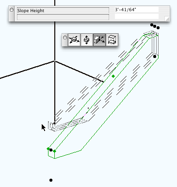
The slope angle can be edited in 3D by two methods. The hotspot in the middle of the beam edits the angle directly. The two hotspots at the bottom end edit the change in elevation. Tip/note: You will probably only edit the slope in 3D for hips and valleys; the slope of these doesn't need to be precise, just right enough that they don't stick out. Another: for hips and valleys, I frequently turn the model off. For rafter elements within roofs, it's better to set the slope in the settings.
Text Label:
The label will describe the stock and number of members if greater than one. You can choose to label the beam generically, and set the generic text. If "DBL JOIST" is on, two-member beams will be labeled "DBL JOIST" and three-member beams will be labeled "TPL JOIST". If the object is sloped, it will be labeled "RAFTER" instead. You can also add text to the label, e.g., ridge, hip, valley, flush, dropped, etc.
If "'Below' Note" is on and the object is set to display on the story above, "BELOW" is added to the text when seen on the upper story.
If the label is on the "wrong" side of the beam, mirror the object along its axis. The text should flip correctly for any rotation and mirroring.
Labeling in section:
The beam can be labeled using Description JAM9.