
Most of the advice about sections and elevations applies to interior elevations as well. We do interior elevations because the larger scale lets us show more information. Some of this information is already in the model and the scale change reveals it. Some of it is fine modeling that doesn't need to be done until you start the interiors. Some is very fine detail that is done in 2D within IE windows.
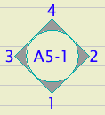
Use the interior elevation tool. It's fussy but it works. I recommend always using the polygon method, never the single line method. There are two reasons for this. First, often you think you only need to elevate one wall of a room, but later you need another wall. Second, polygon IEs are easier to select because you can grab them by the marker.
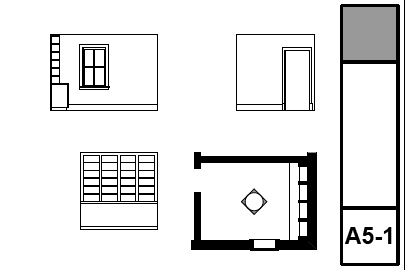
Scale: 1/2".
Output pen set: '*Layout', same as sections and elevations. The poché is gray.
Layer Combination: A5 Interior Elevs There are few changes from the A2/3 Elev+Sect+Detail combination. S Beam is hidden. Generally, IEs are about finishes, not structure. L Grade is hidden. We're not concerned with anything outside the walls. E Fixt3 is showing, while in the 1/4" sections it is hidden. Use this layer for modeled wall sconces, switches, and outlets which you want to see in the interiors.
In the CDs subset, there is a folder called A5 Interior Elevations. Within this folder there are clones for the Interior Elevations (made by the IE tool) and for the Elevations (in case you need to use elevations).
In the layout book, there is a subset for IE sheets within the CDs subset. IE sheets are the A5 series. This subset is included in all the CDs publisher sets.
Trim: All of our trim objects are scale sensitive. They will automatically present more detail in the profiles at 1/2" scale than at 1/4" scale, assuming the Niceness parameter is set to 'Auto'. This applies to the Crown Tool, Baseboard Tool, wainscot, Trim Panel, door and window casings, pretty much everything.
Cabinetry: It is very easy to get cabinetry, including kitchen cabinets, bookshelves, and other built-ins, looking good at 1/4" scale. For base and upper kitchen cabinets, use Cab Blob JM10. For countertops and other surfaces, use a slab. For bookshelves, use a thick wall with a flock of Cabinet Opening JM9.
The Cab Blob doesn't do doors directly. However, you can turn the Front Panel off, put a thin wall in its place, and put Cab Door doors in the wall. This door is in 12 Furnishings / Casework. This sort of modeling can wait until you start work on the interiors; until then, you can use a plain Cab Blob with the front panel on. Do everything when you need to.
Electrical: Fixtures on E Fixt3 will show in interior elevations, but will be hidden in building sections. It's a good idea to show the outlets and switches using Receptacle Wall JAM81 and SwitchMultiJAM81 with the 3D parameter on. These objects also draw the symbols for the electrical plan. There are also a couple of simple sconces in the Electrical Fixtures folder, but it's likely that you will end up drawing something better in 2D.
Just like anywhere else, you model what you can and draw what you can't. 1/4" sections should require very little 2D work, but interiors may need a lot, depending on the design details.
Cabinets are the biggest issue here. Cabinets vary so much in design that it is prohibitive to offer model objects that meet all of our needs. So, always use Cab Blobs, use Cab Door doors when you can, and draw the rest.
You also might have to draw light fixtures. You might have to draw anything! The point is, at interiors scale, it becomes very hard to offer complete model tools for every detail of every thing.
Call everything out, as usual.
Mouldings and many objects can be labelled automatically with the label General Element Label JM20. The Description option will call out the basic identity of many objects such as railings and decorative columns. The Moulding option is specifically for moulding objects such as crown, base, panels, etc. The independent Description label, currently version 19, also works.
Use linked detail markers to refer to to trim and cabinetry details. It's convenient to copy and paste these markers between interior elevations.
Interiors sheets are the A5 series. You can start with A5-0 or A5-1. If you can get all the IEs for each story on one sheet, you can use A5-0 for basement IEs, etc.
In AC11, drawings (not just interiors) have the ability to auto-arrange themselves on a layout. It sort of works, but you will still need to do some moving around. The best way to understand this is just to do it; grab some drawings and drag them to a layout all at once.
The spacing, from the sheet edge and between drawings, is controlled by the master layout, in the 'Auto-Arrange Setup.'
New drawings are added after the last drawing if any are present, regardless of whether there is space above.
If you drag a group of interior elevation views, the order on the sheet is not sensible. If you drag multiple room groups at the same time, each room will begin on a 'new line' regardless of how much space is available. If you drag rooms one at a time, the latter groups will follow the last drawing and go from there.
I think the auto-arrange is more of trick than a real feature, given that you will probably to do a lot of adjustments. But it is a quick way to get a lot of drawings on a sheet just to see what they look like. Interior sheets are probably the only place you would try this; most other sheets have 1-4 drawings, while detail sheets are arranged by the grid.
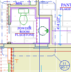
There is a layer combination for enlarged plans, A5 Enlarged Plan.
In the templates, there is an A5 Enlarged Plans clone within the CDs subset. Once you drop the plan in the layout, you will need to adjust the frame of the drawing to fit the room. Unlike 1/4" plans, enlarged plans should use the drawing element's title. You will probably have to edit the name of the drawing to something more descriptive than 'First Floor', e.g.