
With an assist from Brian Spears and Link Ellis, I figured out that one of my wishes for the mesh tool is already solved. So I thought I would take the opportunity to revise this overview of the tool.
The most prominent use for the mesh is site modeling. I cover that in more detail in another post, but you need the mesh basics first.
A mesh is a like a slab with a bumpy top. Without the bumpiness, it is indistinguishable from a slab. It's a polygon with three materials and one pen for plan and 3D. (There is another pen for the non-user ridges in plan. I very rarely want to see those, and precisely never for a site model.) The mesh doesn't interact with the floor plan cut plane and it doesn't have overhead pens. It has a cover fill, but unlike a roof, the fill won't distort along a slope.
The construction methods of the mesh tool are surface-only, hollow, and solid. You'll hardly ever use anything but solid. The others are only surfaces and can't be used for solid operations. We wish for a thickened-surface road-type construction method.
Meshes, like slabs, have a reference plane which defines the element's elevation position. For slabs, the ref plane has a fixed relationship to the element. It is either the top or bottom of either the whole element or the composite's core.
For meshes, the ref plane is more abstract. The bottom of the mesh, which is flat, is positioned by the thickness setting, relative to the ref plane. The bumps on the top are defined by individual Z values of polygons, polylines, and single points, relative to the ref plane. Two things to keep in mind, though: One, it is possible to vary the thickness and the Z values to create geometrically identical meshes that have different ref plane elevations. (Like you can have identical roofs with different pivot line positions.) Two, you have the option of defining Z values relative to working levels in the project, such as project zero or sea level, rather than the ref plane itself. In practice, the position of the ref plane isn't as important as the actual geometry of the top and bottom.
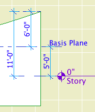
This mesh has a thickness of 10'-0" and is placed at 5'-0" above the story, which is equal to project zero. Please pardon the term 'basis plane', that's the old name for the reference plane and I didn't want to redo the screenshots just for that.
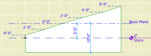
Reference plane, I mean. Reference plane.
The thickness needs to great enough to accommodate the lowest elevation of any point on the top, or the mesh will go surface-only. If your lowest elevation is -4'-0", you need a thickness of at least 4'-0".
It is possible to do an upside-down mesh with the bumps facing down, by using a negative value for the thickness.
Mesh point elevations can be edited in plan with precision and efficiency, in 3D with precision and poor efficiency, and in section/elevation not at all.
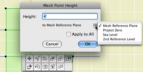
In plan, the polygon palette associated with nodes has an extra button which will open the mesh point height dialog. Here you can enter the elevation relative to the ref plane, project zero, or sea level, or other reference level.
You will also get the button on an edge. When you set the height of an edge, that height is used for the nodes at both ends of the line.
The 'Apply To All' checkbox controls whether the height edit will affect just the current point or all the points of the polyline or polygon. 'All' doesn't mean the whole mesh element, just the connected points that were drawn together. The mesh polygon is an 'all', as is a hole, or an individual contour. Usually you will Apply To All when editing contour elevations, and usually not when editing the mesh polygon.
Height editing is also available in the 3D window, but it's different. You can set the height of a point graphically by aligning it with another 3D element.
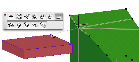
There is no mesh point height dialog, but you can type Z to enter a height relative to project zero, sea level, or the current user origin, by changing the elevation value origin in the tracker or coordinate box. You can't use the mesh ref plane. The most frustrating limitation in 3D is the absence of 'Apply to All'. You can only edit one point at a time at a node, or two by clicking on a line segment. This is a show-stopper for working with topographic contours.
Note that a vertical surface is not allowed, because that would require coincident contours at different heights. For a vertical surface, use a wall or a slab edge. For tunnels or overpass conditions, you need multiple meshes or solid operations.
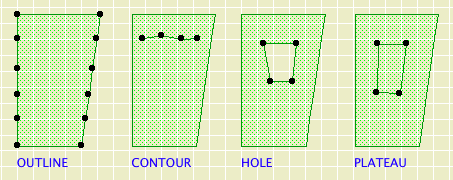
Adding points to a mesh is just like editing any other polygon element, up to a point. Use the palette to add edge points. Draw a polygon within a selected mesh to create a hole.
Here the mesh becomes special. If you draw a new polygon within a mesh, you get a dialog box asking if you want to create a hole or add new points. The latter option can be used to create a plateau of a given elevation. And, such a new geometry does not have to be closed; it can be a polyline. Of course, you can magic-wand any extant geometry to create new points.
In the New Mesh Points dialog, there is also a pulldown with options for how the default elevation of the new points should be set. 'Fit to User Ridges' means the points will be interpolated between the Z values of points you have already defined. This places the new points 'on the ground' between your other elevations. 'Fit to All Ridges' does the same thing, except it also considers the intermediate triangles that Archicad inserted to make your geometry join up. In practice, you can end up with extra nodes that don't represent user data, so avoid this option.
The remaining option, 'No Surface Fitting', is the place I recently learned something valuable and got to delete a wish. To explain, we need to jump ahead to how site models are usually made. Basically, you create the overall mesh polygon, then add contours along the topo lines. Due to limitations of the mesh tool, you have to draw 2D contours for the site plan using splines or polylines, so it is convenient to magic-wand mesh contours onto these 2D elements. This gives a new node at the intersection between the contour and the mesh polygon. This node should rise and fall with the contour when you change its Z value, but it will only do so if you use 'No Surface Fitting'. If you use 'Fit to User Ridges', the new node is considered part of the mesh polygon, and has to be edited separately.
From a user perspective, that node should absolutely always be considered part of the contour, and the 'Fit to User Ridges' behavior is destructive of user data. But that is a wish for another time.
If you are placing incidental points and contours within a site model, use 'Fit to User Ridges'. When developing the contours initially, use 'No Surface Fitting', and set the Z value of each one as you go, making sure 'Apply To All' is checked.
Subpolygons can be selected independently from the mesh as a whole by clicking on an edge. If you select by a node you will get the whole mesh. To delete a contour or other subpolygon, just select it by an edge and strike delete.
You can create a single node within the mesh by double-clicking on a point with the pac-man (first) geometry method.
Kinds of All
In plan the mesh appears as a polygon, with lines at the 'User-Defined Ridges', as the polylines and polygons are known in the settings. If you show 'All Ridges' in plan, you get triangulation lines. I don't see the appeal of this, most days.
The mesh has limited plan attributes. There's one pen for the polygon and the 'Ridges', and another for the triangulation junk that I leave off anyway. There's only one linetype for everything. It can display a cover fill, but there's no foreshortening distortion due to slope.
In order for the mesh to meet site plan standards, we would need separate pens and linetypes for the perimeter and the contours. Further, the contours need to be allowed to curve and spline. (Whether they can truly curve in 3D is another question wish.)
There's another graphical issue in 3D and elevation. The 'Model Ridges' setting allows you to show the triangulation junk ('All Ridges Sharp'), hide the junk ('User Defined Sharp'), or hide everything ('All Ridges Smooth'). Oh wait, that doesn't work. 'All Ridges Smooth' is the same as 'User Defined Sharp'. (The only place you'll see a difference is in photorendering.) If your elevation is looking uphill, you will see horizontal contour lines. Again, if we had more attribute flexibility, we could set the contours to a non-printing pen.
• Independent plan attributes for the boundary and contours.
• Curved contours, in plan at the very least.
• Give contours priority at nodes shared with edges. Solved by 'No Surface Fitting'.
• 'Apply to All' for contour heights in 3D.
• Hide contours in elevation.
• Thick surface (road) construction method.
• Allow vertical surfaces.
Beyond the scope of the tool as designed, advanced features would include composite skins, more blobbiness (contours on all sides), and some sort of accessory capability. The mesh as it stands is primarily a (weak) terrain modeler, while for free-form modeling we have the Morph.