MacDonald is a long-completed new home project. I don't know how long, but the important thing is that it's an AC7 project. We are reviving it for the purpose of some interior renovation. Naturally, we want to use the data we have. There are a few issues in working on a project of this vintage:

• All of the elements on new (.N) layers need to be treated as existing.

• The libraries.

• There's a couple of minor pen issues, to the extent that pen issues can be minor.

• The project is full of CD-phase annotation. All we want is the geometry.

More»


I built this newel out of ordinary stuff. Crown and baseboard objects, walls, a mesh for the top. In plan, there's a square fill. All the elements go on the layers they would if placed directly in the project. The model parts are on A Stair3, and the fill is on A Stair Rail.

The newel is all alone in a separate project file. I hotlinked it into the main house project, and copied it around. There are eight of them.

It is easier to maintain than if I had saved the whole thing as an object, which was my first idea.

I am also using the newel PLN to generate the section and elevation details of the newel. Can't do that with an object. Remember you can have drawing links to different projects.

When I needed a half-version of the newel: I created yet another separate, blank project, and hotlinked the newel into that too. Then I placed a big slab and SEO-subtracted away half the newel. Then I realized that the plan fill was still whole, which is no good. I broke the hotlink, which leaves ordinary elements. (So I could have simply merged it after all.) I adjusted the fill to cover only half the newel. Then I hotlinked the half-newel project into the main house as above. (If I change the whole newel, I'll have to do the half over. Not ideal, but the alternatives aren't either.)

Something to think about...

I've added an 'Alternates' folder to zTemplate folder, in 1 Design. It should have been there before, sorry.

It gives me an opportunity to discuss alternate handling, or at least to give you one case study. Vassos, although it's under construction, has occasional lapses into design development. The clients were interested in seeing alternatives for one part of an elevation. We offered two, which forked into three.

I saved a copy of the project for each alternate, with a descriptive name, in that Alternates folder. I developed the model for each alternate. We wanted to present a perspective and an elevation for each choice. Since the alternates are in separate files, and all the alternates are separate from the main PLN, it's easy to simply use the views you already have. You can't mess anything up.

To present the choices, I created a new subset in the main layout book. There's no reason to create separate 'books for each. Within the new folder, there are two layouts for each alternate. I hooked the new layouts to the 11x17 Master. Then I imported the perspective and elevation views from each PLN.

Once the decision had been made about which version to use, it was time to begin treating that scheme as the real project. I renamed the main PLN, which had been untouched, with a date, and moved it to the '6 Old Files' folder. I saved-as the anointed alternate with the original name of the main PLN, at the top of the project folder. This means the layout book never knows anything happened. If you change the name of the project, you will need to re-link your views.

In the end, we have three alternate PLNs set aside, the pre-alternate version of the project intact, and the layout book not disrupted. And a compact record of the alternates' presentation. Pretty good.

In this case I was fortunate that, since the project was 'done', there was no other work going on anywhere. Presenting alternates in the DD phase is trickier, especially if the design decision is slow in coming. If you need to keep the main project moving while the alternates are being developed, it is better to merge the chosen alternate elements back into the main project.

I've added a new layer combination to the templates, 'Stretch House'. It's intended to help when marquee-stretching the whole project. It simply shows and unlocks everything building related, while hiding the section markers and everything site-related. I hope you find it useful, or can at least ignore it.

If you search Google for a simple question with a concrete, factual answer, it will give that answer ahead of all the usual links.

For example, I just put in 'how many square feet in an acre' and got '1 acre = 43 560 square feet'. Thanks, that's what I needed, bye. Other recent applications include comparing the land areas of Maryland and El Salvador. El Salvador is twice as big. And the Earth weighs 5.98x1024 kilos.

This is everything I can think of.

More»

If you drag a dimension string, the texts will re-center themselves on their segments, assuming the texts have not been moved manually.

You don't actually have to drag the string anywhere, just a drag and a double-click will do it.

The only way a dim text would be off center without you moving it is if you customized the text.

Who cares? You, because you probably changed some texts to read EQ or something, and re-centering them by hand is a cumulative chore.

So, after changing the texts to read whatever, (deselect the texts,) select the string, Cmd+D, clickclick. Note: if the dimension tool is active (very likely), you have to do a Drag command; cursor-drag will edit the witness line length. You can drag with the arrow tool and it works; I think the Cmd+D method is better since you don't have to be precise. Any texts that you moved manually will stay put. AC remembers which those are.

I just dimensioned all the Vassos ceiling lights on the electrical plan, which, if you've never had the pleasure, boils down to a LOT of EQ EQ EQ EQ EQ. So I was really happy with this discovery.

Sort of cross-posted here.

(Originally posted here. Added examples.)

Here is the Geometry Methods info box tile.


Geometry Methods are the ways of making a shape with a tool. The 'GMs' are only available in the info box, not in the settings. You can switch geometry methods in any tool by typing G.

The first button is one click placement. The object will be created with the default X, Y, and rotation. Example: A recessed light fixture, since it's not stretchy and it doesn't matter how it's rotated.

Second is rotated placement. Two clicks. First is anchor point, second is angle. X & Y will be the defaults. Examples: Anything that you would turn to face a certain direction. A lot of things. Sinks. Light switches. Sconces. Centerline symbols.

Third is rectangle placement. Two clicks. First is anchor point. Second is the diagonally opposite point. The same method is available for polygons (slabs, fills, etc.) Not all objects will be placable this way; only stretchy* ones. By this method you can graphically set X & Y, but you can't give values. Example: Crown Tool in coffer mode.

*Interlude: Stretchiness. Objects are stretchy if they have hotspots in their 2D scripts at the 0, A, & B extents, OR "Hotspots on bounding box" is on in their "Details". Don't worry about this now. An example of a stretchy object is Bed 01 in the Furniture folder. The only way to know if an object is stretchy is to try it, or look in the script. Most rectangular objects should be stretchy.

For "stretchy" placement to work, you have to have a corner set as the insertion node in the settings. If a non-stretchy node (e.g., the center) is the insertion node, you get one-click simple placement. In the plan preview window in the object settings, the insertion node has a box around it. You can choose a different insertion node there by clicking on it.

Tip: When you Option-click (pick up settings) on an object, the node you clicked becomes the insertion node.

The fourth button is rotated rectangle. Three clicks. First is the anchor point. Second is angle AND length of first side (X). Third is length of second side (Y). Example: Crown tool coffer in a rotated space. The same method is available for polygons. If a non-stretchy node (e.g., the center) is the insertion node, you get two-click rotated placement.

The key is not to get hung up on "rotated". I use this method all the time for non-rotated polygons, because you can use R to set the length of both sides on the fly. Example: counter slabs. When placing an object such as a bathtub this way, you need to know which way the object goes; X is first, Y is second. If you do it backwards you get the drain on the long side.

If an object is "linear", only stretchable in one direction, stretchy placement still works. If using rotated placement (4th), the second click only sets the angle, and the third click sets the length. Using the fourth button with a linear object enables you to draw it very much like you would a line. Examples: Lots. Drawing title, crown tool in straight mode, steel and wood beams, cut lines. Sometimes it's hard to predict which side of the "line" an object will be drawn; if it's wrong just mirror it.

Choosing the right geometry method saves a lot of after-rotating and -stretching, and is therefore much faster.

You can magic-wand a zone stamp to place a polygon using the geometry of the zone itself. It works even if the zone polygon is hidden, and saves you the trouble of finding an edge, since zone edges tend to coincide with lots of other stuff. Magic-wanding the middle of a room is often impractical due to interference of other lines.

Handy for finish-floor slabs, lower-the-ceiling-in-one-room slabs, floor material fills, etc. Just make sure your zones are updated first.

Cross-posted here.

I was going to patch up this post, but I decided to do a new one. The old one is mostly right, I just wanted to add...

• In AC9, there is a menu command for Create Independent Detail. That means you can have a shortcut for it. In our keyboard setup, it's Ctrl+D. (What. Oh. Tools menu. Please don't do it that way. I hate menus.) Also nice, when you create an independent detail, it opens automatically.

• For some reason, most of my projects open new independent details at absurdly zoomed-out views. Like the window is a million feet across. I can't fix this, it's not stored in the prefs. It's always a good idea to work near the origin. You can zoom to the origin quickly by placing an object there and then doing a fit it window.

• Wall sections should be Sections. It's so clear to me now.

• IDs. They still need to be unique, but the ID will now take up to 31 characters, so you can be very non-cryptic. You can have spaces, though I don't use them. I like it to be clear that the first word is the ID. To review, use the ID to say what type of detail is in there, with a number so maintain uniqueness. Use the name for a fuller description. Eave1 Typical, Eave2 Shed, Eave3 Porch.

I have been drawing all the engineering details myself, based on their sketches. I keep these separate by beginning all their IDs with "S_".

• Detail markers: For areas, use Detail Area JAM9. For flags, use Detail Flag JAM81. These markers show the ID in ArchiCAD and the drawing/sheet number in PM layouts. For assemblies, use Assembly Marker JAM81. This marker maintains the ID, which is the same as the (non-autotext) drawing number in each assembly detail. It also gives the sheet number, which is automatic. I have developed the habit of putting my schedules and assemblies on sheet A3-1, so they stay put as sheets are added.

• Remember you can open a detail from any marker, not just the original one.

• The biggest hassle with the detail tool is the fact that you can't put a detail marker in a detail window. Maybe someday. If you need to call out a detail within a detail, use an object. Remember the autotext referencing hack.

Once I put up that screenshot of the detail marker, I noticed that the gibberish components of the two autotexts are the same. The difference lies in the DRAWINGNUMBER_R and LAYOUTNUMBER_R tags at the front.

This means I can have reference markers (section and detail flags) that just need to be told the gibberish segment once, and can build the autotexts themselves. For these objects, instead of copying the entire autotext in PlotMaker, just copy the data within the second pair of angle brackets: "<9BEA5D4E-8700-11D8-8AA9-000A95A7B33A>".

I have added this ability to Detail Area JAM9. In the settings, paste the gibberish into the "Paste Autotext Here" field. In the drawing and layout number fields above, you will see the completed autotext fill in. You can still put non-auto text in these fields; if you delete the "Pasted" data, the fields will empty and unlock, and you can use them however you want.

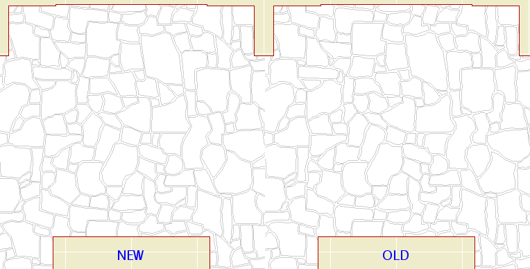
I redrew the "Flagstone Random" fill pattern, in an attempt to get it to redraw faster in vectorial. I cut the number of lines by about 50%. There are now only 1700 lines in a 10' x 6' rectangle.

It's a little faster. Not as much as I expected, but every little bit yada yada.

If you want to try it, you can pull it from the Vassos project using Attribute Manager. Here's the before and after:


I think the new one looks better too.

If no one complains I will replace the fill in the templates in a little while.

I was happily (!?!) putting in the rake mouldings for the gambrels on Vassos. On the sixth one, the outer rake failed to subtract from the steep roof of the gambrel. All the others had worked. Imagine my joy when I saw that all five previous subtractions at the same condition had also failed.

The "solution" is to slightly change the edge angle of the upper roof edge. In my case, the angle of the edge when mitered to the upper roof was 74.3651º. I rounded up to the nearest hundredth of a degree, to 74.3700º. To keep the section through the miter looking presentable, I had to change the adjacent edge angle of the upper roof.

Over time I have have seen these subtractions continue to deteriorate, and I have to change the angles again. It's a pain, but there is no other way to model complex rakes.

Remember that it's very easy to drag drawings between layouts while in Tree by Subsets view.

If you have a big pile of new drawings (details, interior elevations) destined for multiple sheets, import them all at once into one layout. Then distribute them by dragging them in the tree.

Q
When I paste elements, is there a way to select those elements?

A
Complete the paste. Undo (Cmd+Z). Redo (Cmd+Shift+Z).

Q
Working in section, is there a way to reveal selected elements in plan?

A
Yes.

Q
How can I tell what elements were affected by a marquee stretch?

A
Undo, redo. The affected elements are selected. Current story only, natch.

When an editing action is undone, the edited element will typically be selected. Comes in handy.

Why: Same reason as always. Model views are more consistent and easier to maintain. Modeling is the better way to work things out for real. You can block up passable wall sections earlier without sacrificing consistency. To get them graphically perfect will require conversion to drawing in the end, but you can put it off at least through design development.

How: Lots of 2D fills, lines, and objects placed over empty model elements. You were going to use all that 2D stuff anyway. A lot of the fill-placement is to make up for the fact that composites can't be scale sensitive yet.

More»

Everybody knows this, right?

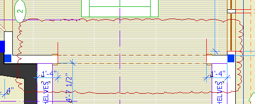
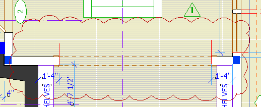
Do not use the "Cloud" objects in the ArchiCAD library. They are the worst objects in the world.

Clouds should be drawn with a closed spline using the "cloud" linetype. The only glitch is that sometimes the cloud will be inside out when you are done. If this happens mirror the cloud, or, if the shape is non-mirror-friendly, draw the spline again, in the opposite direction. Sometimes the spline doesn't quite close. Pretend not to notice.

For the triangle, use the object Character+Shape JAM8. The number comes from the ID.


Bad cloud. Looks like a chunk of foam rubber from an AirTran pillow. Also missing marker.


Pretty cloud, reminds one of heaven.

It's slow to open the settings dialog when you can use the info box.

It's slow to choose File -> Save rather than typing Cmd+S.

It's slow to choose File -> Merge rather than typing Opt+M.

It's slow to hunt down the close button at the top of a window rather than typing Cmd+W. However: it's slow to bring a window to the foreground so you can close it, if you can click its close button in the background.

It's starfish-slow to choose Edit -> Copy, choose Options -> Stories -> Go Up A Story, choose Edit -> Paste, rather than holding down Cmd and typing C, 6, V.

It's canyon-formation-slow to choose Tools -> Display Order -> Bring Forward, Tools -> Display Order -> Bring Forward, Tools -> Display Order -> Bring Forward, Tools -> Display Order -> Bring Forward, rather than holding down Ctrl and typing 6, 6, 6, 6.

It's slow to right-click and choose Undo, right-click and choose Undo, right-click and choose Undo, right-click and choose Undo, right-click and choose Undo, rather than holding down Cmd and typing Z, Z, Z, Z, Z.

It's slow to drag windows around until you see the one you want rather than use Exposé.

It's slow to go to Display Options when you can use this.

It's slow to go to the Project Map, scroll to the Details part, right-click on it, and choose New Independent Detail, rather than typing Ctrl+D.

It's slow to right-click and choose Open Section/Elevation, or Last Section/Elevation, but unfortunately we don't have a choice.

The fastest way to cancel anything is to type Esc.

The fastest way to deselect is to type Esc.

The fastest way to remove marquee is to type Esc.

The fastest way to switch to the Arrow is to type Esc. The second fastest way is to type Right Arrow, and that's better a lot of the times because it doesn't require that you have no selection and no marquee.

The fastest way to activate the Marquee tool is to type ` (the key above Tab).

The fastest way to activate the Wall tool is to type 1.

The fastest way to activate the Slab tool is to type 2.

The fastest way to activate the Roof tool is to type 3.

The fastest way to activate the Text tool is to type E.

The fastest way to activate the Fill tool is to type F.

The fastest way to activate the Door or Window tool is to type D or W respectively.

The fastest way to change the reference line side of a wall is to type C.

The fastest way to change the geometry method (box, rotated box, polygon, etc) of any tool is to type G. It's also the fastest way to switch the orientation of the dimension tool.

The fastest way to turn on gravity and choose the gravity element type is to type V.

You can do all those things without moving your left arm. You have to move your left arm a little, but it's still fastest to

...activate the arc tool by typing 0 (zero),

...activate the Object tool by typing (letter) O,

...activate the line tool by typing L,

...activate the Dimension tool by typing /.

...toggle the rotated grid by typing K.

Plenty more where those came from.

I will try to flesh this out when I have time. It's a solid method, and touches on a lot of useful techniques.

• 3 coincident walls for fire box: Stone veneer, block core, fire brick. All go on A Fireplace.

• Use roof for back of fire box; SEO add to firebrick wall. Roof goes on X SEO General.

• SEO Subtract firebrick assembly from core. Subtract FB assembly and core from veneer.

• On top of firebox, 2 slabs or walls, one inside the other, veneer and core. Both go on A Chimney3. Subtract core from veneer.

• Smoke chamber: Mesh. connect firebox void to smoke chamber with slab. Both go on X Flue. Use print-white pens. Subtract both from the core Chimney3 element.

• Flue: Object, Flue JM9. Can be plumb or offset. Build the flue out of segments, attach to smoke chamber, work your way up. Some flues will show in plan, check the "Show Cut" box in settings.

• Subtract the flues from everything they pass through.

• Use slabs for hearths, adjust Chimney3 elements as needed. Fill in with Chimney3 walls or slabs as needed.

You can copy and paste elements between facing sections/elevations, and easily put the pasted elements in the right place. Examples: Room names in sections, and elevation outlines.

The trick is to mirror the elements across the global origin.

More»

Hotspots do two things:

1. Placing a detectable point where there isn't one.

2. Making a point detectable in PlotMaker, for the purpose of aligning drawings to one another or to the layout.

In practice, I use very few hotspots. I try only to use them where they will be permanent. A common example is a hotspot at the maximum of a curved wall, so the wall can be dimensioned.


Such permanent hotspots should be locked.

I almost never use them as a workaround, and if I do, I delete them immediately. If you get in the habit of placing a lot of hotspots and leaving them around, the workspace becomes cluttered with extra detectable points, making it harder to be sure you are detecting the point you want, leading to errors.

Further, hotspotting an arbitrary point to detect it is usually not needed. Special snap points and the ghost story make it possible to detect any point worth detecting, and you can move the origin to "transmit" a point through stories. You can also use CenterPoint JAM9 as a hotspot, and it has the added benefit of showing on multiple stories. And really, how often do you need to detect a point that's truly in the middle of nowhere?

If you've gone on a hotspot binge for whatever reason, you can delete them all at once: Activate the tool, Select All (Cmd+A), delete. Since your permanent hotspots are locked, the won't be harmed in the purge.

Hotspots are also created by certain variants of command clicking. This has occasional usefulness, but it more often happens by accident, so you should be aware of it so you don't wonder how you made a hotspot without the hotspot tool.

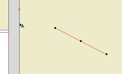
The hotspot on the wall is in line with the red line:


To place a spot like this, select the line, activate any tool except the line or arrow tools, and Cmd+click on the wall.

If the arrow tool was active, nothing would happen. (I think this is a bug.) If the line tool was active, the line would extend to the wall. (Cmd+click acts like adjust where the active tool matches the selected element.)

In most cases, I would just extend the line.

A truly, I think, useless feature crops up when you Cmd+click on a roof edge instead of a corner, when trying to find the height of a roof at a point. You get a hotspot at both corners bounding the clicked edge. And you don't get the height box, which should tell you you're doing something wrong.

While hotspots are usually low-utility in modeling, they are almost required in laying out sheets. Hotspots are visible and detectable in drawings placed in layouts. They cannot be printed. When placing alignment hotspots, use a prints-black pen (I like 5), so you see them against the white of the layout area and the grey of the rest of the window. Some applications:

� Hotspots at the corners of the drawing area in the plan window, for aligning the plans on the sheets. Since all the plans will use them, they should be on the ArchiCAD layer. The templates have drawing area objects and hotspots for each sheet size. You'll probably need to move them to frame your project correctly. Though the object shows on all stories, the spots need to moved on each story. Alternately, you can move one group and copy it to the other stories, deleting the old ones. These spots should be grouped and locked. In PM, you may have to resize the drawing frame to fit these spots.

� The drawing area matches the available layout area within the title block. There should be hotspots in the title block at the four corners of the big empty space. There should also be spots at the center of the sheet number box, and the left edge of the (optional) sheet title box. In the templates this is done.

� Use hotspots to align drawings as they are aligned in the building, such as two wall sections next to each other, or parts of the same wall section. Place hotspots on a common point of both drawings, such as a wall or floor plane, then drag the drawings in PM to align the spots.

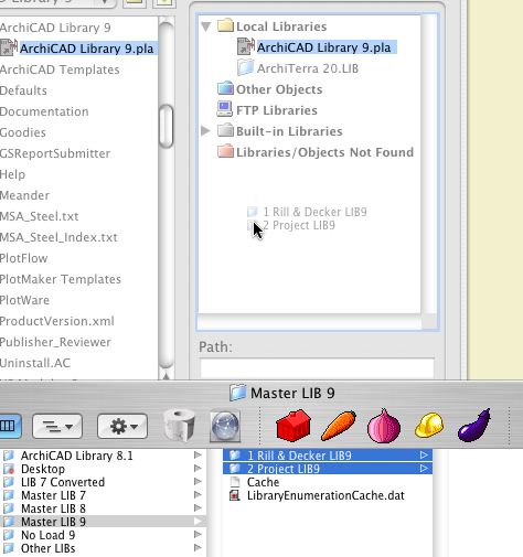
You can drag and drop libraries to the Library Manager from the Finder.


Like this

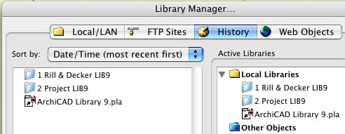
In Library Manager, the History tab shows the libraries that have been loaded recently (since the last Clear or Clear All). This list is independent of any particular project.

Typically we use the exact same libraries all the time. But there are exceptions; sometimes you need the version 7 library, for example. If you've loaded that library recently, you can add it from the history tab instead of scrolling through the whole Local/LAN tree.

It's also helpful if you take projects home. When you open a project in a different location, the library manager will come up because the servers aren't there and your local ArchiCAD folder path is different. But the history tab remembers the local instances of the libraries, making it easy to load them quickly.


If you load a "wrong" library at some point, you can use the "Clear" button to delete it from the history so you're not tempted by it in the future.

A particularly self-starting member of the ArchiCAD community, Karl Ottenstein, has developed an add-on called QuickDisplay, which allows us to assign keyboard shortcuts to various display options. The commands are toggles, which means you can strike a key turn the Section Depth (e.g.) on, and then strike the same key to turn them off. He has generously allowed this add-on to be used free of charge. Here is the ArchiCAD Talk topic where mad, righteous praise is heaped upon him.

Here is Karl's page with full instructions for the add-on. I will summarize the high points.

Get the file from 3 Resources : Add-Ons. Place it in your local Applications : Graphisoft : ArchiCAD 9 : Add-Ons. Launch or relaunch ArchiCAD.

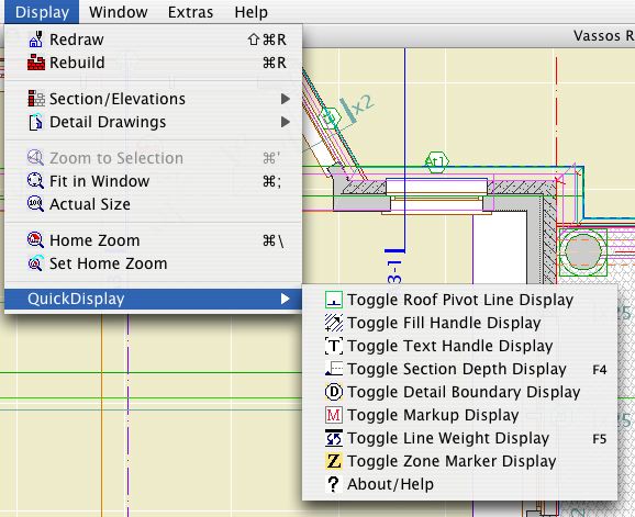
Your Display menu should now have a QuickDisplay submenu at the end. Here you will see commands for toggling various display options.


QuickDisplay Submenu

Naturally, and I hope obviously, you don't go to this menu to activate the commands. That wouldn't be much of a shortcut would it. The commands have to be on a menu in order to have shortcuts assigned to them.

As you can see, I only have shortcuts assigned to two of the commands, Section Depth and Line Weights, on F4 and F5 respectively. I toggle the others much less and I don't need a shortcut for them. You can do whatever you want.

I have updated the RND Keyboard scheme with these two shortcuts. You can import the updated scheme at Options -> Work Environment. The scheme is located at 3 Resources : Work Environment : RND Profile : Shortcuts.

For information on assigning shortcuts, see the ArchiCAD Reference Guide, page 153, or ask for help.

The question is, when you change the height of a door or window, does the head or the sill move. In real life, we want the head of the door to change, but the sill of the window. In olden days the sill would control no matter what. In AC8, they offered a preference, but it applied to both openings, so either the door or the window still behaved wrong, which if you think about it is no improvement at all.

Now, in AC9, they have it straightened out:


Options -> Preferences -> Construction Elements

Here's a new trim layer. It shows in the same layer combinations as the other 'F Trim'. In addition, it shows in the reflected ceiling plan, which is the point.

Place Crown Tool objects on this layer and you can avoid redrawing the crown for the RCP.

The layer has been added to the templates. Add it to current projects if you like. More on creating layers here.

Why?
1. Maybe you want to email it somewhere (like home).
2. Smaller files are more reliable. Less chance of corruption.
3. They save and open faster.

How?

More»

OK I should have done the foundation stuff in the meeting today because it would have given me the opportunity to demonstrate polygon editing for walls, lines, etc.

More»

You can't place a detail marker in a detail window. Rats.

You can change the linked drawing of a placed marker by opening the settings and clicking 'Browse' underneath the detail name.

I've updated the other post with this info.

On the ArchiCAD Help Menu, beneath the first two items, you will find two lists of items.

The first list consists of links to PDFs, including the ArchiCAD manuals. The PDFs reside in the Documentation folder within the ArchiCAD folder. Any PDF placed in this folder will appear in the menu.

The second consists of links to web sites. The links reside in the WWWLinks folder within the ArchiCAD folder. Any link placed in this folder will appear in the menu.

What it does:

Limits the area for a Find & Select.

Limits the area for a Select All, or a tool-specific Select All.

Limits the model displayed in the 3D window.

Marquee-stretches. Elements wholly within are dragged, elements partly within are stretched. Groups off!

Limits the elements to save as a module. With heavy marquee, makes it possible to save a multi-story module.

Limits the print area, instead of resizing the window.

Makes it possible to show section perspectives.

Remember that with a marquee placed, everything in side the marquee is selected for any purpose other than changing settings. All the transformations and copy transformations will work. Delete will work. Eek!

See Also:
ArchiCAD User Guide 2 pg. 14

Some are redundant. I will probably think of more.

• Use the 'Working Dims Plan' Layer combination.
• Option+click on existing strings to maintain witness line justification as you move in.
• To add one string's ticks to another, select the string to keep and Cmd+click on the string with the points to add.
• Use the arbitrary angle setting when dimensioning walls, for auto-orientation.
• Use the 'place, rotate, drop' construction method with the CL object.
• To graphically justify a group of witness lines: Select the ticks. With the dimension tool, click on the segment and drag it to the desired justification point. Useful for backing up a few witness lines where the plan is very near.
• When you select a tick, the element the tick is connected to will briefly show as selected. To maintain this effect long enough to actually observe it, hold the mouse button down on the tick.
• Ticks can accumulate at a single point. If you try to delete a tick and i stays put, keep trying.

See also:
Dimensioning, General Principles

Favorites are preset configurations of the tools. They enable you to quickly configure a tool for a given purpose, like option-clicking without the need for a placed element.

I have never developed a strong affection for them, for several reasons. They were terribly implemented when they started, in AC6.5 if memory serves. Until AC8, there was no button for favorites in the settings box (?!!). Finally, in a far-along project, option-clicking is still the fastest method. Modules are also nice.

In AC8 the feature is mature enough that I can recommend you try it.

More»

You have clicked some points for your dimension string. You have not checked the geometry method for the correct orientation, horizontal or vertical. Well over half the time, due to Murphy's Law, the wrong one is selected. You click to place the string, and get nothing. You have to start over. You are sad.

If you are dimensioning walls, you should be clicking on the line of the wall, rather than the corner, in order to dimension the core. (This isn't the tip; it is current standard practice. I hope someone is praying for you if you aren't dimensioning this way.) Choose the third, arbitrary angle, geometry method. With this setting, the string is forced to orient perpendicular to the wall, regardless of the wall's direction.

For two strings with the same orientation, select one, then Cmd+click on the other. The second string will disappear, and its points will be added to the selected string.

Forgot something else...

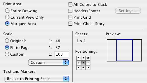
In 8.1, we have the option of placing a marquee to limit the print area, instead of fiddling with the window itself.


Print Marquee Area, among other things.

Click 'Copies and Pages' and select 'ArchiCAD' to view these options.

As far as I know, this option has always existed, but I've only fully internalized it recently.

Try this display option in your working plans and sections views:


Uniform Solid and friends

It causes walls in plan, and all elements in section, to display as solid fill of the pen of the fill pattern. In plan, this means that only the corner of the wall itself can be detected, not the inside drywall corner. This eliminates the problem of accidentally aligning counters, floor fills, and such to the core of a stud wall.

I have taken the liberty of changing the working views in the templates to employ this option.

This is about four years old but I wanted to explicitly point it out...

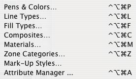
All the attribute-related options on the Options menu (Pens and Colors, Line Types, etc.) use the Ctrl+Opt+Cmd modifier combination with the initial letter of the attribute.


I'm sensing a pattern.


Oh! Those three.

Window | Floating Palettes | Show Quick Layers (Ctrl+L).


Quick Layers Palette

The Quick Layers palette enables you to:

Unhelpfully:

• Toggle the display of all the layers. All the showing layers become hidden, all the hidden layers show. Shrug.

• Ditto for lock/unlock. Shrug.

Very helpfully, under 'Selection's Layer':

• Hide, lock, or unlock the layer of selected elements, even for multiple layers at a time. Similar to the 'Layer' sub-context menu.


Remember?

Unhelpfully again:

• Hide or lock all layers. Big shrug.

The palette will close when you quit ArchiCAD, unlike the standard palettes. Just reactivate it when you start with Ctrl+L.

I've added a module for Site Plan info to the Modules folder (in 3 Resources). It contains all the elements for contours, boundaries, notes, etc. I did not include separate note stuff for the 120 & 240 Note layers, but you'll probably live. N.B.: 8.1 only!

Don't forget: In AC8, the escape key now performs the cancel function. This makes it consistent with all other software in the solar system. 99% of the time, hitting ESC will be faster than mousing over to the Cancel button, or right-click-canceling.

It's also another beautiful, inspiring, timeless, indestructible tower on the magisterial edifice that is The Keyboard, as compared to the moldy-straw-1st-little-pig-shack of Mousing Around Clicking Buttons, Menus, Sub-menus, and Sub-sub-menus.

In other words, learn the shortcuts, and use them. And we'll plan our escape.

LOON ISLAND, ME -- Due to the wet spring and summer, the lake is a good 18-24" higher this year. Remember that the dock is simply resting on the lakebed and is not tied down in any way. If not kept above the water, it can blow away in high wind/waves. The idea is to elevate the whole thing while moving it closer to the shore. Keep in mind:

The dock is heavy. You will need three or four people.

You will get wet.

Wear shoes that can get wet, and that will stay on your feet; there's some mucky spots on the lake bottom.

There are rocks. This is good, because you will need to put them under the feet of the dock to elevate it. It's also bad, because you will have to lift the dock far over some of them.

The dock is built in sections that can be taken apart and moved separately. The only wrench is an adjustable one, there aren't any sockets in the cabin. The nuts are under the dock which is awkward. Remember 'Righty Loosey Lefty Tighty' because the nuts are upside down. Try not to drop the nuts in the lake.

What? Oh! No, no, no, not that dock. That's in the System Preferences under 'Dock.'

Perhaps you are looking at an element in an S/E window, and want to find the element in the plan.

Select the element in the section. Drag it somewhere. Undo. Return to the plan. The element will be selected. Or, delete it, and Undo.

Caveat: The plan window must be on a story where the element is showing. Use Zoom to Selection to find it. If Zoom to Selection shows only the S/E element, you're on the wrong story.

Here's a summary of the single key commands in ArchiCAD. I didn't know some of them either. G & C will save you a lot of mouse milage.

  • A - Activates the Angle Coordintate
  • B - Activates the Base Value (in the Info Box)
  • C - Cycles through the Construction Methods
  • D - Activates the Divisions Snap Option**
  • G - Cycles through the Geometry Methods
  • H - Activates the Angle Bisector Modifiers**
  • O - Activates and switches between Offset and Multiple Offset**
  • P - Activates and switches between Parallel and Perpendicular Modifiers**
  • Q - Cycles through the Quick Alignment Methods (when Shift-constraining)
  • R - Activates the Radial Coordinate
  • S - Cycles through the Grid Snap Options (former esc function)
  • T - Activates the Top Value (in the Info Box)
  • X - Activates the X Coordinate
  • Y - Activates the Y Coordinate
  • Z - Activates the Z Coordinate
  • 2 - Pans Left
  • 4 - Pans Down
  • 6 - Pans Right
  • 8 - Pans Up

** Broken in OS X. Too bad, epecially P.

You're in an S/E window and you want to change something in the settings of that S/E. Go back to the plan, right? Nope, double-click the S/E tool in the toolbox!