
Location: 06 Wood & Plastic/Trim & Moulding
New version of the main moulding object.
Listen, you will have dozens or hundreds of Crown Tool elements in a project. The object is designed to be used all the time. I.e., it does a lot. Get familiar with what it can do. If it doesn't do something you need, speak up!
This version: There are additional 'shapes' and more parts available. New shapes:
• "J"; like "U" with an independent length for the third segment.
• Rakes, including curved rakes.
• Arch.
New parts:
• Wall Backer 2. Placed behind the Wall Backer.
• Crown Cap. Placed below the crown.
• Soffit. Flat piece placed above the ceiling backer. You will often need this to help the rakes cut the roof edges.
I regret to inform you that I can't continue support the custom interface panel at this time, so we're stuck with the parameter list. Essentially, all this stuff is hard enough to simply get working, and the user interface development tech is painfully disrespectful to time constraints. I have to choose between features and interface and it isn't a hard choice. If this makes you unhappy reread the new features list above and cheer up!
Full documentation below the fold.
Feature Summary
Moulding profile, object shape, mitering and returns with graphical editing, backer mouldings at wall and ceiling, half-round bead and wall backer cap, crown cap, scale sensitive profiles and fills.
These are the parts:
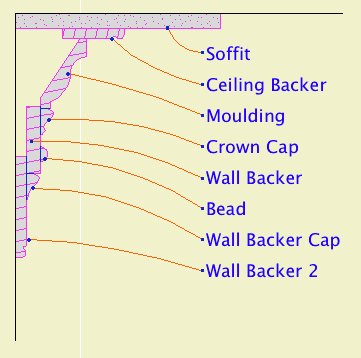
Profiles
Most parts offer a list of commonly used shapes from the Smoot book. I can add new shapes as you need them. Custom shapes are feasible. I have a decent moulding-creation scheme that isn't automatic but isn't a killer either. Ask.
The backers use baseboard profiles. The soffit (rectangular) and bead (half-round) don't have profiles, only dimensions. All the backers can be 'custom', allowing you to set the thickness manually.
For all the backers and the soffit, the actual width is driven by the associated 'reveal' parameter.
Some base profiles come in groups with different heights. If you choose a base profile for a backer, the object can automatically switch to a different size of the same profile, to fit the reveal.
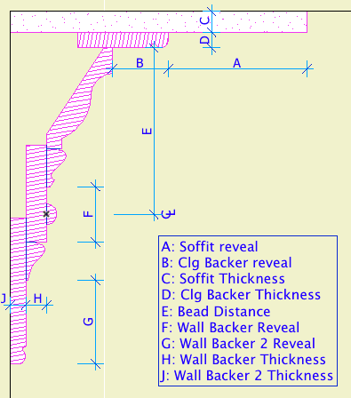
Here's how the dimension parameters relate to the parts:
Shapes
A 'shape' is an arrangement of extrusions. The simplest one is 'Straight'; it's just one segment. Many of the others have multiple segments, so you place fewer objects to cover the same areas. Shapes can further be Interior or Exterior. No, it isn't about exposure to weather! It refers to which side of the object's polyline the mouldings are built on. Kinda like a wall's reference line.
These are the level shapes. The rakes and arch are different and we'll get to them in a minute:
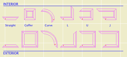
Shapes in plan
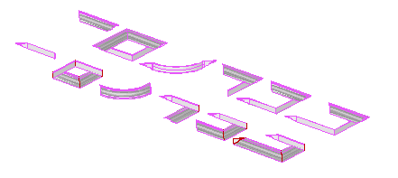
The crown armada
Update March 8, 2010: Utah, right triangle, and angled bay shapes.
For all of the level shapes, you can turn the whole object upside-down using the Mirror on Z Axis checkbox.
You can roll the object along its X axis using the Roll Angle parameter.
The coffer shape gives the option of building a 'ceiling' above the moulding itself, which lets you model the drywall or other ceiling finish. The other shapes don't have this setting, but the Soffit does something similar.
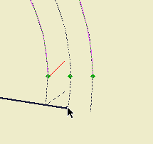
The curve shape has several special parameters. It can have straight 'legs' at the start and/or end. These legs are graphically editable, see below. The resolution of the curve can be controlled directly with the Facets parameter, or you can set the Tolerance (how far off the curve can the segments get).
Niceness There are four levels of quality, plus an 'Auto' setting. Typically, you can leave the niceness set to 'Auto', and let the scale control the quality.
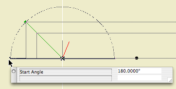
Miters and Returns Either end of any level shape (except the coffer, of course) can be set to any miter angle. These angles are editable in plan. You can also have returns. Turn on the return graphically by stretching the angle past 180.
Rake Shapes
In plan the rakes look like straight shapes. Rakes have all the same parts as the other shapes, but they can't have miters or returns. The big difference with rakes is managing the slope and the angle at each end.
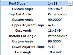
Rake parameters
For the Top (or Bottom) Cut Angle, we have Vertical, Horizontal, Perpendicular, Calculate, and Custom. The first three are obvious, and Custom is simply custom. Calculate uses the Upper (or Lower) Adjacent Slope to calculate the angle where it meets another rake.
Where two rakes meet, give the upper rake the slope of the lower one, and the lower rake the slope of the upper one, and they should get along fine.
Tip: Wherever possible, copy and paste angles between things!
The Rake angle and length can be edited in 3D, similar to the new baseboard.
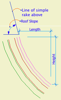
Curve Rake dimensions
The curve depends on three parameters: The Roof Slope of the rake above, the curve Height, and the curve Length. Setup here can be tricky. You shouldn't get an error very often, but you can easily back yourself into a corner where it seems it just won't curve no matter what you do. Tip: Look at an elevation to figure out the height and length. If all three parameters match the elevation, it should work.
If the curve isn't smooth enough, increase the Facets or decrease the Tolerance.
The Bottom Cut Angle can be Horizontal or Perpendicular.
Note: The Curve Rake won't do a symmetrical arch shape. For that you need:
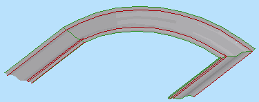
Arch Shape
The arch uses the ordinary length parameter, and the Arch Hgt at Bottom to set the height. Like the curve rake, you'll need to view the condition in elevation and draw some arcs to figure out this parameter.
The ends of the arch are perpendicular and that's it. For an arched dormer: Place an arch crown on the front, and a straight crown object on each side. Give the straight pieces a Roll Angle. (Again, cut a section and figure it out.) Switch on the returns on the front ends of the sides. Switch off end lines as needed.
Scale Sensitivity
Section at large and small scales
At building section scales (1/4", 1/2"), the back of the crown is 'filled in' so the crown, wall, and ceiling should clean up. (Use 'Empty Fill' for the section fill of the object.)
At wall section scales (3/4") and larger, the crown pieces will be shown in section with true profiles, and wood fills. These section fills can be changed in the object's parameter list under the 'Detail Fills' heading.
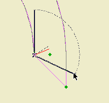
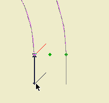
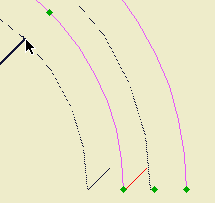
Plan Display and Editing
The 2D view of the crown shows the overall width of the object with the miters and returns. If there is a ceiling backer and/or soffit, there will be an additional line at the edge of the crown itself.
Consistent with our standard, the 'start' end of the object is identifiable by its short red line.
The back line of the 2D symbol (against the wall) can be turned off. I honestly don't remember why I did this, but it doesn't hurt anything.
There are hotspots at each corner and at the midpoint of each leg. The front edge of the object is detectable. This should make selecting a particular object much easier.
As described above, the miters and returns are editable in plan. The curve shape has some unique editing features.
Ceiling Fill (AC11)
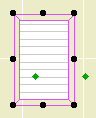
In Archicad 11, we have a new Model View Options switch to put the plan in 'ceiling mode'. (For more on the ceiling switch, check the Ceiling Line JM11 post.) With the Coffer shape, the crown tool can show a fill which will only appear in reflected ceiling plan. If you turn on Fill Origin you can move the origin and rotate the fill using the editing nodes.
Usage Tips
• Use the layer F Trim Crown to display crown objects in RCP.
• Use the L, U, and J shapes as much as you can. They save a lot of time. Use L in corners, and U to go around fireplaces or into a niche.

• Mirror mouldings across corners.
• A 45 degree bay will have miters of 67.5 and 112.5 degrees. A 30 degree bay will have miters of 60 and 120 degrees. When editing miters, remember TAB enables you to input values directly.