On Land

Environment Information
At Rill & Decker Architects we run ArchiCAD on Mac OS X. If you work at Rill & Decker, this is your stuff. If you don't, but you work in ArchiCAD, you may find something interesting. Anybody else, I don't know.
RSS
July 2005 Archive

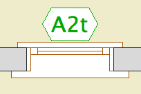
Location: Doesn't matter; window & door markers are selected from the flyout in the info box or the 'dimension marker' tab of the settings dialog.

WindowTag: When the ID doesn't fit in the regular hexagon, the shape elongates to accommodate it.


DoorTag: I fixed that upside-down text thing, I'm pretty sure. I took out the Flip Text parameter. If it gives you any trouble let me know.

2005-07-29.jpg

Location: 13 Special Construction

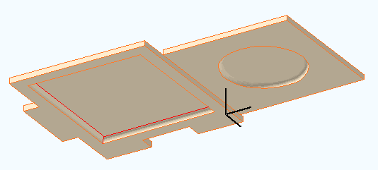
Two objects (primarily) for cutting coved recesses into ceilings, using solid element operations. One's a circle, one's a rectangle. Guess which is which. The parameters of each are similar.

The fillet radius must be less than or equal to the height. The resolution of the fillet is controlled by the Fillet Facets parameter. For the disc, the Resol parameter controls the resolution of the circle.

You can turn the objects upside-down with Flip Z. I can't imagine many cases for doing so, but you never know.

In practice, your ceiling slab will be the target, and the object will be the operator.


Location: 06 Wood & Plastic/Trim & Moulding

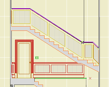
Exactly like the other recent panel objects. This one is a parallelogram suitable for going along stairs. It's a window, and should be used with a thin wall.


The height is the height of the vertical sides, not the overall height.

The slope can be set either by entering the angle or the rise and run. Note: Stair Stringer JAM8 knows its angle in degrees. You can copy it from the settings and paste it into the panel's settings.

It's one of those things that's easier to edit in a section window. Remember windows and doors can be stretched and copied in section.

It looks slightly different in plan from Trim Panel JM9. The handle lines point in the downward-sloping direction.

This isn't a new layer so much as a fork of the old A Roof layer.

In AC9, as everyone knows, model polygons can have a cover fill. This means generally much less drawing, and more showing of those model elements in plan. It also gives the opportunity to 'stack' model elements in plan using Display Order (Send forward/back.)

In AC8.1 and earlier, you might have placed a counter slab on a A Cabs3, and a fill on A Cabs2, now you can have just the slab on A Cabs2. This promotes unity.

This ability, of course, extends to roof elements. It is possible, with some work, to show a roof plan built from actual roofs. This technique will have its own post.

Where we used to have one layer for roofs, because they were all 3D-only, now we have two, so we can choose to show roofs in plan, or not. We maintain the pattern of other 2D/3D layer pairs: Deck2/Deck3, Cabs2/Cabs3, Stair2/Stair3, etc.

The layer +Z Room Name is no longer with us. Dust to dust. Polvo a polvo. Room name objects in plan should go on the layer +Z Zones. This is the layer for zones of rooms. If you use zones, the stamp becomes the room name. If you don't, you can still use that layer for the object.

In passing, I will encourage you again to use zones.

Room names in section still go on +A Arch Note Reg Scale.

(This is for AC9. 10 is here.)

What happens when the existing drawings are done.

The basic idea is to keep the existing conditions, both the PLN and the layout book, tucked away safely. It is theoretically possible to get existing drawings out of the addition project, but it's more trouble than it's worth.

More»

I will use a new home in this description. Existing drawings are very similar. Warning: This is a whopper.

More»

(So Jon says, where's the existing template, and I tell him, and he says I looked online and I didn't see that, and I said, well I'll fix it, so here ya go. The library names were wrong too!)

1. Duplicate the zTemplate folder and rename it with the project name. To duplicate a folder, drag and drop it within the same window while holding down the Option key. Use the client name. If this is a second, or later, project, add a number. (Please don't use roman numerals, they are hard to read.) If it's a sub-project or related project, add a descriptive term. Examples: Stevens. Kernan3. Salamander Garage.

2. Open the project file template for new home or addition. The template names end in .tpl. The new template is at the top of the project folder. The existing template is in the '4 Site & Existing Conditions' folder.

3. In the library manager, make sure you have 'ArchiCAD Library 9.pla', '1 Rill & Decker LIB9', and '2 Project LIB9' loaded. Click 'Library Cache Settings' and make sure 'Use a Local Copy' is UNchecked. Click 'OK' and 'Done'.

4. Once the libraries load, Save As. Format: ArchiCAD Project File. For the name use the client name, similar to the folder name. For an existing house use 'Existing Somebody.PLN'.

5. Go to the Finder and delete the project templates from your project folder. They are no longer needed. If by some weird chance you need a template again, you can always get it from the zTemplate folder.

6. Get busy!
Alphabetical by name of thing. Please suggest improvements and additions. Note: I change the date whenever I update this, so it will pop up every now and then. Rest assured it's not all new. Big changes will have a post of their own.

Changes in this update: S Wall layers, the fireplace stuff, A Roof2 (roofs in plan), CenterLine & CenterPoint objects, gross area calculation, room name object moves to A Zones.

More»

Location: 06 Wood & Plastic/Trim & Moulding

Identical to Trim Panel JM9 and Trim Panel Ceiling JM9, except it's a skylight. And since it's a skylight, it can only be rectangular.

(Q: Why don't you give the ceiling version a slope parameter, then we could subtract from roofs and have all the shapes? A: Good idea, but you can only subtract straight down. You would need to subtract in an angled direction. A wish.)

The 'height' is stretchable in 3D. The height is stretchable in plan too, though the plan view is foreshortened. Further, the plan image shows the shape at the bottom of the roof, what you'd want to see in the RCP. But the hole in the roof is displayed as seen from the top; they won't align, don't worry about it.

Location: 06 Wood & Plastic/Trim & Moulding

Identical to Trim Panel JM9, except it's an object instead of a window, and it lays flat.

It's for putting panels in slabs, for ceilings.


No, it can't actually cut the hole. You have to do that, using SEOs. Target: slab, operator: panel object. Subtract with downwards extrusion. (There is evidence of a SLABHOLE capability in AC, but it is not realized.)

You can choose to show it in the RCP by putting on the layer F Trim Crown.

The 'cut' shapes are editable in plan.

You can show a fill inside the plan polygon.