On Land

Environment Information
At Rill Architects we run Archicad on macOS. If you work at Rill, this is your stuff. If you don't, but you work in Archicad, you may find something interesting. Anybody else, I don't know.
RSS

Element Transfer Settings is a new feature of Archicad 21. It allows the user much greater control over what settings are injected during a syringe operation and/or when favorites are applied. I haven't explored the feature enough yet to be inspired by what it can do, but I think it's going to be helpful.

But I have a problem with the way the feature behaves in projects migrated from Archicad 20. When you open a project in Archicad 21 the first time, a single ETS option is created, Transfer All Settings. As you would guess, every setting in every tool is checked off. This includes settings that didn't transfer in Archicad 20, such as story, ID, and zone name and number. These are the personally annoying results that drew my attention:

• Favorites are set to include the story. So on every story except the home story when the favorite was created, you will get that wonderful dialog box about changes on an unseen story, and then you undo, fix the story, and do it over. (In 20 this just behaved badly and acted like a bug. It works perfectly now once you know what ETS is.)

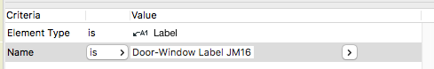
• ID is included, so if you use unique IDs to schedule elements such as doors and windows, you are going to start to see duplicate IDs (i.e., data loss) from using favorites or the syringe.

• I don't think I've ever eyedropper/syringed a zone, but if I did, I wouldn't want the name and number to transfer, that's crazy.

The old way in Archicad 20 offered some control over these things, so if you wanted to transfer ID via favorite you could, though you couldn't via syringe. (That's really confusing and the new way is better, once you know about it.)

So a migrating user of Archicad 21 is probably going to encounter frustration and data loss, before they even meet the new feature that is responsible. The migration process should have created a safer default ETS option. Note, this is only an issue with migration - the templates have a sensible assortment of options.

I have only made a few ETS options so far, but my default one excludes story, ID, name, number, reference ID, title, and label text content. I have a separate option to transfer label content. And I renamed the bad one to: 'Transfer All Settings BE CAREFUL'.

We use labels to show the ID of doors and windows in elevations. The labels are identical to the marker tags used in plan, and the pointer is left off.

With the pointer off, it makes no difference whether you use the single-click or three-click geometry method.

geometry method
Doesn't help

The label will be placed at a (non-user-modifiable) distance from the user-clicked point. (The text appears the same place if you use the single-click method with the pointer on.) Since that clicked point must be on the door/window in order to place the associative label, the label itself will usually show up off to the side of the opening. Then you have to move it into place on the opening.

offset label
Wrong

(The way it should work: With the single click method and the pointer off, the label should be placed where the user clicked. This is one of those design issues that is so obvious I just call it a bug, opinions vary.)

Here is my best compromise method. Turn the pointer on. Use the three-click geometry method. Put the first click anywhere on the opening. Put the second click level with the point where you want the label. (After this click the Y coordinate is set.) Put the third click precisely where you want the label.

pointer label
Wrong, but be patient

Label all the openings in the elevation. Use find and select to select all the labels by name.

find and select
These ones

Turn the pointers off. The labels are off-center with the pointers on, but they will center on the third point with the pointers off.

good label
Done

Much faster than adjusting each one.

This clever trick from Patrick May at 4dProof about labeling zones in section has two parts. The clever part is the lateral thinking of labeling things in the zones rather than the zone itself. The other part is the introduction of autotexts in labels in Archicad 21.

The lateral thinking part could have been discovered versions ago, you just needed to script the label in GDL because there was no label autotext.

So when I got done slapping my forehead I wrote a label in Archicad 20 which matches our zone stamp and the object we have been using to 'label' rooms in section. And while the label autotext is very handy, but, as always, GDL gives you more power and control.

First, let's review the clever trick. You can't label, or even detect, zones in section or elevation. What you can do is label a model element, and have the label state what zone an element is in. (Related zone condition is determined in plan. The elevation of elements and the height of zones doesn't matter.) Turn the pointer off, and you have a word which is the name of the room floating in the room. The label is live data - if you rename the zone, the section labels will be updated. And, you don't need to know the name of the room to label it.

These element types can report their related zone:
• Object
• Lamp
• Morph
• Beam
• Column
• Stair
• Wall, if zone boundary, with caveats

These element types are ineligible:
• Slab
• Roof
• Shell
• Wall, within zone
• Door
• Window
• Skylight
• Railing (AC21)

To label the room, you need to find an eligible element in it. In our projects, considering that not every room needs to be labeled, almost every room has a lamp, object (moulding, appliance, plumbing fixture, etc), or beam in it. If there are none of these in a room, I suspect the project isn't far enough along to be labeling rooms in section.

The main walls of the room, since they are usually boundary walls, are a good choice with caveats. There may be two (or more) zones related to the wall, so you need to be sure the right one is shown. In Archicad 20, sometimes there are two zones available and the label just ignores one of them. (This seems to be fixed in Archicad 21.) If the walls won't cooperate, you'll need to find something else to label.

Room names in section

The basics described so far also apply to labeling with autotext in Archicad 21. These are the additional features of this scripted label:

It precisely matches our standard for room names, including the fussy underline and the ability to 'stack' two-word names.

It can show the name and the number or both, and the font and size of these texts can be different.

It tries to help if you label something ineligible. If you label an ineligible element, there is no text to display. In this case the autotext label just sits there, blank and invisible. Go ahead, place a bunch of empty labels until you notice the pattern! The scripted label helpfully states 'something is wrong' in this case. (The two things that can be wrong are that the element is of an ineligible type, or it is not inside a zone. GDL doesn't offer the ability to tell these conditions apart, otherwise I would have the label tell you.)

If you are labeling zone boundary walls, you can switch between the two zones the label knows about. (Autotext only offers one zone and no way to switch that I can see.) There is a checkbox in settings for using the 'other' zone, and even better there is a graphical switch at the top of the text block. (It only appears for walls with zone zones.) Switching doesn't always help: Since walls can bound more than two zones, the one you want might not be offered. You'll need to label something else.

Update, July 7, 2017
Only the main properties (name, number, etc) of the zone are available to labels. Our zone stamp has additional parameters, such as an optional short name which can be shown in small rooms. These parameters aren't available to the label, so you can't use the short name for rooms that are small in section. In that case you can make the text size smaller or use the number instead.

I have tweaked the label so it behaves more civilized in the settings dialog.

Download

Here's a general solution to dashed lines in 3D. Line types aren't available in 3D GDL. I'm using this for hinge lines on doors and windows.

Dashed Line 3D

More»

An unheralded new feature of Archicad 20 was a repair to the Mac version where Archicad will continually hunt on the network for missing servers. This happens when 1) the project uses resources (libraries, external drawings, hotlinked modules) on server volumes, and 2) you open the project away from the network where the servers reside. The effect is 1) a delay when opening the project as the external resources are sought, and 2) periodic warning dialogs saying that a server with a certain IP address cannot be found.

This has been a problem since at least Archicad 9, or maybe forever and that's when I started carrying projects around. I was always told it was hard to reproduce or impossible to fix, and it doesn't happen on Windows. (I mean, they never told me the Windows thing, that's just a fact.)

In Archicad 20 it was definitely fixed for a while, and there was great celebration all around, uh, my kitchen table which is supposedly one of the few places the problem occurs. Then it returned, likely an unintended consequence of an update. I am led to believe that now the issue is impossible to reproduce, so I'm not holding by breath on a fix. I think that was the shot.

So we still need DisableCrossPlatformMountingFeatures. If you are a Mac user and this situation affects you, close Archicad, open Terminal, and paste this in:

defaults write com.graphisoft.AC-64\ 20.0.0\ USA\ v1 InputOutput -dict "DisableCrossPlatformMountingFeatures" "<true/>"

This will work for any version of Archicad back to 15, just replace the '20' with the relevant version number. (Before that, drop the '-64', and for heaven's sake please upgrade.)

Let's just say I have a feeling the next version might be in the same boat, so for your clipboard convenience:

defaults write com.graphisoft.AC-64\ 21.0.0\ USA\ v1 InputOutput -dict "DisableCrossPlatformMountingFeatures" "<true/>"

Click to enlarge.


dormer illustration


Wordier version from AC10 here.

Location: 32 Exterior Improvements /

Update: Japan and Alaska.

I needed a US flag, and I didn't have my own, so I searched in the settings dialog. The US Archicad Library doesn't have one either. There is one on BIMComponents, written by Graphisoft, and maybe that one is in the international version library. It's just as well, because the object (Flag.gsm) doesn't offer the US design.

In fact, it doesn't name any countries. It is charmingly purely parametric: Choose the number of stripes, their direction, and their surfaces. In this way, they can cover lots of the flags of Europe. There is also a cross option to address Scandinavia. UK? Haha no.

This Graphisoft flag looks really good. It is waving, compound waving even, and it droops just a bit. The code is classic morphbarf, though I wouldn't know how to create such a morph in native Archicad. It was likely done in a proper freeform modeler, imported to a morph, and then saved as an object. Their trick is to slice up the waving flag geometry with CUTPLANEs in various proportions and directions, depending on those non-national parameters, and then apply colors to the slices. So Hungary and France and everyone have different stripes with the exact same waving.

But now we can see why there is no US, UK, or Canada version. The stripes and crosses are all simple straight cuts, and sometimes flags need closed and nested polygons, many of them. When I have to weave together a lot of weird geometry, I head for the group operations, the GDL equivalent of SEOs.

I appropriated the morphbarf and abandoned the rest. (The license on Flag.gsm is Attribution-No Derivatives, but the editor offers limited choices - seems like ShareAlike would be better. Graphisoft please get in touch if you have any concerns.) The operations used are subtraction (SUBGROUP) and intersection (ISECTGROUP). The flag parts' geometries are made via PRISM_, and the trick there is to slope them down to match the droop of the morph. (Tip: (-1) * SIN(droopAngle) * horizontalDistance) Some shapes are subtracted from others, such as the stars in the blue fields. Then each finalized PRISM_ is intersected with the morph geometry, which creates chunks of waving stuff with the different colors.

flags

The leaf translation required some thinking, but I developed a general method that should come in handy again.

In exchange for the morphbarf I am happy to offer the finial and the tapered pole.

As of this writing I have the US (needed), Texas (so simple, and someone might need it), Puerto Rico (requested), and Canada (who doesn't like Canada). Next is probably DC (easy, local) and Alaska (I just like that one). Japan? Having done the maple leaf, I can see the UK from here, which would lead to AUS and NZ. Anything with a fancy seal or heraldry (Mexico, half the US states) will require different techniques. Staying away from Maryland for now.

Download here.

Sheet A2-1
Everything I can think of about sections and elevations.

More»

Happy anniversary to this post from October 16, 2006. That's the year of Archicad 10.

The post is called Ways Objects Have to Be Right. (I should have said library parts, I regret the error.) There were a lot back then:

  • Plan symbol
  • Plan symbol on remote stories
  • 3D hidden line
  • 3D shaded
  • 3D render
  • Elevation
  • Elevation in distant area
  • Section
  • Polygon efficiency
  • Scale sensitivity; which compounds the plan symbol, section, and polygon issues
  • Listing
  • Labeling
  • User interface
  • Parameter list
  • Parameter transfer management (Unique parameters)
  • 2D graphical editing
  • 3D graphical editing
  • Selectability
  • Code maintainability
  • Intra-library consistency

And that's still most of them. The user interface options have become more complex, and the new rigor around using certain global variables in the parameter script has been disruptive, but most of my day to day concerns are on the old list.

At the time I noted that the GDL editing environment ignores a lot of well-established GDL features:

The development environment gives very poor support for many of these requirements. As Archicad adds features, items are added to this list. Irritatingly, the environment has not kept up, and is way overdue for a tear-down. There is no section window, no remote stories, no graphical editing. The full features of the current GDL architecture are not supported, so we can't even imagine modern development features such as syntax coloring and auto-completion.

To that I would add: Cutting, wallhole (and later wallhole2) and solid geometry operations.

Ten years later, the GDL environment is practically unchanged. Not entirely: You can create a new parameter in the middle of the list, and you can search for a parameter name. They ironically gave the hide parameter button a red 'X' for version 20. I'm grateful for two of those and neutral on the third.

But every one of those unsupported features is still unsupported. You still can't Cmd+G to Find Next. The error messages are still deliberately vague. (How many parameters too few, or too many? Which !@#$% variable wasn't initialized?!) Check script still lights up random macro calls, so you have to check again, note the line number, and navigate there yourself.

Frustrating neglect reached a new peak with Archicad 19, as the new tab interface (tabs are great!) couldn't remember that GDL windows should be undocked, always, and no one who had actually worked in GDL would dream otherwise. Archicad 20 is an improvement - The windows stay undocked, but they don't remember their positions and stack order well at all, so there is still a lot of inefficient UI overhead.

When I wrote that post ten years ago, I think I thought there might be a GDL editor section window someday, or that you could see cutting geometry in wireframe. The verdict of history is clear!

I still think GDL is one of the most important features in all of Archicad, and I think it had the potential to be a key technology for custom content in the larger BIM world, though that horse is long out of the barn. No serious developer of anything works with such poor support. At this point, GDL is valuable to our work so I work with it a lot, unable to forget that it's an abandoned 20th century artifact.

With the advent of renovation in Archicad 15, the transition from existing conditions to new construction is much simpler. We still want to finalize and set aside the existing conditions before moving on.

More»