On Land

Environment Information
At Rill Architects we run Archicad on macOS. If you work at Rill, this is your stuff. If you don't, but you work in Archicad, you may find something interesting. Anybody else, I don't know.
RSS

This is a very simple label for duct elements made with the MEP Modeler add-on. It's intended for use with any simple duct type, including Straight, Bend, Take-off, and the Obstruction Fittings (as far as I can tell). I'm using it solely for straight pieces, since no one is fabricating anything from my plans - I just want to coordinate with the HVAC engineer.

For round ducts, the label reads '5" dia'. For rectangular ducts, it reads 'Width x Depth'.

All our ducts are sized in inches, so I'm using a fractional inch format for the dimensions. On the off chance that someone else might find this label useful, I've added a parameter so you can choose to have the label's format match the current dimensions format in the project preferences.

It was convenient to use Select All for the (straight) Duct Tool, then label them all with the Label Selected Elements command (Document -> Document Extras).

Duct Labels

Download

Until now we have done the electrical symbol legend as a hotlinked module of a story, where the lamp and object elements are placed in the floor plan within a table drawn with lines. This is a static resource, unless you break the module hotlink and modify it.

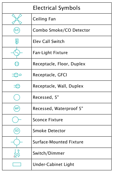
It is possible to create the legend using Interactive Schedule. The advantage of this is that it will only display the symbols that are actually in use. This makes a more compact, relevant, and readable table.

Electrical Symbol Schedule

The schedule itself is very simple. It only shows two columns. The first is the 2D symbol, which is a field/parameter of objects and lamps. The second is a custom parameter of our lighting and electrical objects - the parameter is 'desc' internally, and is called 'Type' in the settings. (A missing feature in most library parts is an ordinary name that can be easily listed and labeled. The object name usually doesn't work, and style options usually go by cryptic handles such as 'Style 1'.)

From here on I will say 'object' while I mean 'object or lamp'.

The schedule merges identical items into one. Remember that the IS only considers displayed information when deciding what is identical. So if the symbol and Type are the same, none of the other parameters matter - you will only get one entry. You have a surface fixture at 8'-0" and one at 9'-0"; they are the same to the schedule.

Simpler objects know what they are out of the box. Ceiling fan, duh. Some objects have options which change their identity. A recessed fixture can be ordinary, waterproof, a heat lamp, adjustable, etc. A smoke detector can be a CO detector, or a combination. The Type parameter should automatically respond to these details. The schedule will list separate items for each of these differences, because the Type field is different. The symbols will be appropriate for each difference.

The electrical switch object will always present itself as a pair of switches, one regular and one dimmer. This is so sets of two, three, four, etc. switches don't show up as separate items. GFCI switches are shown separately. (GDL folks: This is done by drawing a specific case of the symbol when the GLOB_CONTEXT is a schedule. In the future, but starting now, GLOB_CONTEXT is deprecated and you should use GLOB_VIEW_TYPE=9 (Calculation) instead. Since I'm still maintaining our AC18 Library, I can't implement this change yet.)

I had to replace the ceiling fan symbol so it would fit in the same cell height as the others.

Again, when you have your own library, you can do whatever you want.
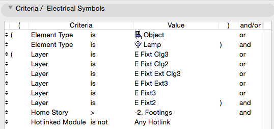
Criteria
Electrical Schedule Criteria

The criteria look more complicated than they are. It's just:

• Objects and Lamps

• On any electrical fixture layer

• But not on the Footings story, because that's where the old legend is placed

• And not part of a hotlinked module. Delete this criterion if the module is not covered by a separate project, and you want to schedule the module's fixtures.
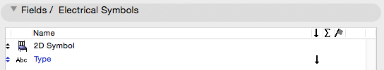
Fields
Electrical Schedule Fields

The fields are only two, as described above. The 2D symbol and the Type:

The schedule is saved as a view in the Schedules folder, alongside the window and door schedules. It should be placed as a drawing on each electrical sheet.

Updated for Archicad 19.

Pen sets let you change the appearance of output at the very last moment - when the drawing, based on the view, is headed out the door. The colors you see while working on the model can be completely different from the published output, and they should be.

More»

Standard pens updated for Archicad 19.

The only substantive change since 2007 is that we've dropped pen 170 for structural posts on the story below. This was an ugly hack that's no longer needed since we can use Library Globals to control display of those elements.

That's a very small change, but I wanted it to be clear that these standards are still current. I updated the graphic. I have strong opinions about pen -1.

More»

Sloppy modeling leads to sloppy documentation. That wall that's supposed to be 7'-0" long, but you built it 7'-0 5/64", so it dimensions at 7'-0 1/8", and the published output looks ridiculous.

Sloppy modeling doesn't clean up right in plan, section, elevation. (It looks fine in OpenGL with contours off. Great.) That means extraneous lines that either mislead the viewer or have to manually managed by you. Not everything cleans up, but everything that can, should. And sloppy modeling does not.

Once you have sloppy elements placed, you will likely refer to them to place other elements, and the slop spreads like a virus.

Sloppy modeling is not easier. This is how you model precisely:

• Use direct entry of distances. This means: Start placement, type 'R' (Hello world: Archicad default is 'D'), enter the distance and strike return.

• To place elements a set distance from a known point, move the origin (Opt+Shift) and use direct entry of X and Y by typing 'X' and 'Y'.

• If you are placing something 'roughly', it's still better to pick a number. Start the wall, e.g., and when it's 'about right', look at the R field (Distance in Tracker) and mentally round off the ugly number there. Then type 'R', enter your rounded distance, and strike return.

• Place the model with a sensible relationship to the global origin. A centerline, a corner, etc. You can reset the user origin to the global origin and 'feel around' with the cursor to see which end of Mr. 7'-0 5/64" is the bad end.

• If you're trying to center something, just center it. Draw any linear element from side to side, find the midpoint, and put something there. I would use a Center Line object because it is distinctive. Lesser but acceptable solutions include hotspots and non-printing lines. (Graphisoft wants you to use the new permanent guide lines, but I'm not a fan.) Whatever the thing, consider locking it. You can also use snap guides in AC19+ to find midpoints, or the old snap points constraint on the Control Box.

• Use a Center Point object to mark the center of curves, to make sure concentric elements are truly concentric. Show on all stories as needed. Lock it.

• Our plan-scale dimension standard is set to 1/8" precision. We only want to see output dimensions of 1/4" precision. (Unless there is an angle involved.) When you expect to see 7'-0" and see 7'-0 1/8" instead, that is your warning that something is off. Track down the 5/64" and fix it.

If any of these things is harder than clicking kinda wherever, I'm not seeing it.

Precise modeling is essential to Archicad success.

This is a new approach to showing openings in reflected ceiling plans, using a modified plan symbol rather than an blank opening. I haven't put it in the template yet, and it may not be required or appropriate for every project, but it is better overall. The biggest limitation is that in order to use it you have to use our doors and windows almost exclusively. This doesn't bother me much.

More»

What to do when the project is done.

First, make sure it's really done. 'Almost', 'practically', 'pretty much', 'just about', and 'I think it's' done are not the same thing.

More»

In the old days, things were different. How different depends on how old the days are. It's hard to anticipate every issue you might encounter in an old project. The first question is, what do you need from the project? Do you need drawings, a detail, or are we actually resuming work on the project?

More»

Leads and pending projects should be placed in 1 Projects / zPending.

These are projects which have no modeling or design data with them. They might be just a proposal.

When a pending project actually begins, create the project folder as normal. Drag any documents in the pending folder to the new project folder. The proposal belongs in '3 Contract & Correspondence / Proposal'. Trash the project's 'pending' folder.

If a project does not go forward, we will move it to 5 Past Projects as part of our quarterly project cleanup.

All the typical layouts (that I can think of) are blocked up in the project templates. Developing the layouts consists mostly of framing the plan, tuning up the section/elevations, and arranging the drawings on the sheets.

More»