
July 2007 Archive
This will go live when we move to Archicad 11. It doesn't have anything to do with 11 per se, but it's easier to make organizational changes at a version break.
On 3 Resources / AC, we have a new folder called External References. This will hold all the external drawing and annotation resources which are used in the templates. These are:
• The Abbreviations PDF on the cover sheet.
• The Drawing Symbols PLN. This generates the views that wind up as the symbol keys on the cover sheet.
• The General Notes PDF for the T2 or T3 sheet.
• Standard assembly detail modules, which are hotlinked into detail windows.
• Probably other things.
This is all the standard stuff. If a project has external references particular to itself, those go in the project folder.
In the current system, if you can call it that, we have these resources in at least three places and it's a hassle if you need to relink something. In the 11 template it's clearer.
What to do when the project is done. (Updated a bit where the project folder structure is concerned.)
First, make sure it's really done. 'Almost', 'practically', 'pretty much', 'just about', and 'I think it's' done are not the same thing.
Here's the ordinary elements by themselves. I put in some detail objects for clarity:
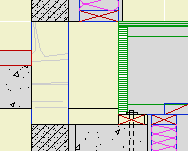
The top of the concrete wall is in the right place for the joists, but it's part of a composite with the stone veneer that needs to reach the bottom of the slab. Likewise, the frame part of the upper composite is right, but the stone needs to come down.
There are several ways to solve this with walls and slabs. I'm not going to go into them, except to say they are all rather unpleasant, typically involving 3-5 elements, some of which will be new composites. Sad work, especially when you have to take the whole mess around a corner.
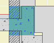
An alternative would be to use fewer elements, get it looking OK-but-not-great, and then use a patch to make it pretty. As you know, you create a patch from existing geometry, and then use 2D editing to force it to look right.
(To be clear, I'm not against patches. They are hacks, but often essential hacks.)
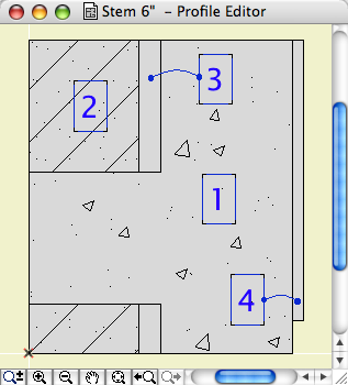
Here's the thing though: If you're going to push fills around to make the condition look right, why not do it in a custom profile? It's still a 2D shortcut, but you end up with a 3D piece you can use wherever you find the condition. It will miter around corners and generally behave like a proper modeling element, displaying correctly no matter where you view it.
A custom profile can be arbitrarily complex, made up of any fills in any shape, and when it's placed it will clean up in section to the like fills it touches. Its surfaces will clean up to like surfaces in elevation.
Such a profile could used with a wall or a beam element. Use a 3D-only layer such as A Wall3. It's probably easier to place the wall/beam on the lower story in this case. If you use a wall for the profile, set its Floor Plan Display to 'Overhead All' so it stays transparent.
Conclusion: If you're facing a multi-fill section patch, see if you could use similar fills in a custom profile instead.