On Land

Environment Information
At Rill & Decker Architects we run ArchiCAD on Mac OS X. If you work at Rill & Decker, this is your stuff. If you don't, but you work in ArchiCAD, you may find something interesting. Anybody else, I don't know.
RSS
Documentation Archive

(1) A custom profile for modeling and (2) an object for annotation.

Profile:
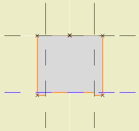
Soffit profile
In the profile editor
• The shape is that of two fascia boards with a reveal of 1/4" below the soffit board.

• The horizontal stretch extents are inside the fascia board reveals. This way, when you adjust the overall width the fascia thickness will be unchanged. Similarly, the vertical stretch extents go from the top to the underside of the soffit, leaving out the reveal.

The custom profile tech only allows you to stretch one dimension horizontally and one vertically. You can exempt parts of the profile from stretching, but you can't stretch them independently. If you want a different reveal depth or fascia thickness, you'll need another profile.

• Profiles can stretched bigger, but not smaller. (I call this a bug, but what do I know.) Any profile you intend to use with varying dimensions needs to match or be *smaller* than the smallest case you have.

• The templates have two profiles, Coffer Beam and Coffer Beam Half. Both are 4" x 2" which should be small enough. The half version has the fascia on only one side and is meant to be placed along a wall.

Remember that profiles are attributes, so they're within the project file, so you can edit them without messing up anybody else. And: You can use Attribute Manager to bring profiles into the current project from the templates.

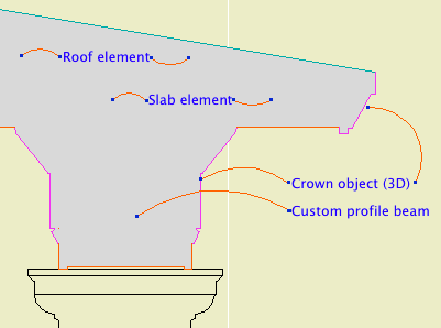
Here is a sample condition at 1/4" scale, no detail added:
1/4 scale soffit

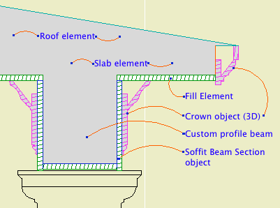
At higher scale, we need to add detail:
3/4 scale soffit

Object: Soffit Beam Section JM10

Location: 06 Wood & Plastic / 2D Wood

The object fits within the profile's perimeter.

Height and width of the object will match that of the beam itself.

• Parameters for Fascia thickness and reveal.

Crown Hgt sets the point at which the pen switches from the object's cut pen to the Separator Pen. In practice this height should meet the bottom of a crown object placed against the beam, which will maintain the heavy outline.
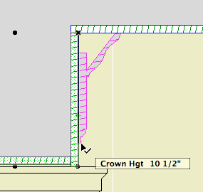
Crown height stretch

• The Half option uses one fascia board to work with the half version of the profile.

Commentary:

We build one model. We take views of the model and annotate them as needed. We will take views of the model at various scales. Scale is fundamental to architectural documentation: As we look closer, we see more.

Yet Archicad lacks any meaningful automatic scale sensitivity, except that written into objects by people who want it such as me.

In this example, see how the crown objects draw themselves as empty blobby things at 1/4" scale, but they're detailed shapes with proper fills at higher scales. The roof, slab, and beam elements, not so much. (Archicad library objects, not so much either.)

Since we can't get conventional AC elements to detail themselves according to scale (yet, I hope I hope), we need to build a model that can accommodate the detail we need to add. This is the idea behind something like the Stud Wall Detail object. The wall is empty, and we place the object in the viewpoints that need it.

The soffit detail described here has always been tricky. If you approximate the beam with a rectangular model, it's difficult to manage the reveal without masking. It's easier to add 2D detail than to subtract modeling.

A custom profile allows us to handle the cased beam in the "Empty Fill +" fashion we are accustomed to with walls, roofs, and floor decks.

Automatic titles are not new to 10, but title objects are new, and now that they are objects, we can use them, which is new.

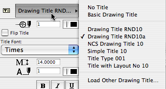
A drawing title is essentially a marker for a drawing element. Like section markers, detail markers, symbol labels, and door/window markers, you choose the title from a popup menu rather than from an object-type browser.

Drawing title list

As with all markers, there's no way to restrict the list. It shows all the loaded drawing titles, and it's up to you to pick the right one.

Elevations, sections, site plans, and details should all use automatic titles. Plans are the only drawing which has an object (Plan Title RND10) in the window. PDFs placed for notes ordinarily shouldn't have a title. Scanned details might, it depends.

Since the title and its settings are part of the drawing element's settings, you can change them in groups using the Drawing Manager. (Note: You must have a layout as the frontmost window to do this; otherwise the title tab is grayed out.)

Drawing Title RND10a is very similar to Drawing Title RND9a. There's a couple of 10-specific changes:

• By default, the title uses the name of the drawing (which should come from the name of the view, which should come from the name of the window). You can put in a custom text under the 'Title' tab in the drawing settings dialog.

• Titles don't have a length parameter like a regular object. So the Length parameter controls the length. You would normally adjust this graphically:

Title stretch

The length still has a minimum equal to the title text length.

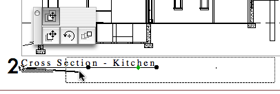
Again I have to apologize for issuing a '10a' revision. There was one issue with Drawing Title RND10 that I couldn't fix in place. That title would appear right on the corner by default. The new one appears 3/8" below the corner, which makes it easier to move the title as needed. Note the 'move marker' palette button:

Drawing drag

And, full disclosure, I broke the minimum length thing, but now that's fixed.

(Heavily revised for AC10, though still a little clunky.) This is the standard workflow for issuing SK drawings.

More»

Location: 01 General / 5 Title & Layout

SK Hints

Very, very simple. A text showing a standard scale, which you can choose from a list. The primary use will be placement in the SK layouts' scale field.

Why? I don't like typing scales. And no, it's not easy to get the scale of the placed drawing automatically, though it should be.

Use it for SK addenda.

The templates have a fax transmittal as part of the layout book.

More»

Date Formats
Options
Location: 01 General / 1 Graphic Symbols

A text object for writing the date.

If Auto Update is on, the date will be read from the system. (Tip: turn it on and then off to get today's date while keeping it from updating by itself tomorrow.) The Year, Month, and Day can be set manually using the pulldowns.

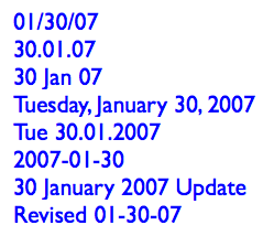
There are a lot of Date Format options. I've tried to cover all the conventions that I know of.

Any of the formats with a separator character will use the character given in Date Separator. You can choose from the list or make something up.

Two-Digit Day will zero-pad single digit days.

Day of Week can be on or off. If it's on, it will be read automatically along with the rest of the Auto Update. It will not fix itself for a manually set date. (It doesn't know the 30th is a Tuesday.) The Format of the day of the week can be long or short. Note that the list will always give the short form. The day of the week can be followed by an arbitrary separator, where the default is a comma.

You can add Leading or Trailing Text.

Text Formatting: All the usual suspects. Font, size. (You can choose mm or points to define the units.) Bold, italic, underline. The object can be anchored by any of the nine typical text block spots, using the Horizontal and Vertical Anchor parameters. You can have a Background Pen and the Outline Pen. Setting either one to zero turns it off. Finally, you can set the Padding between the text and the background/outline polygon. (This uses the same units option as the text size.)

Non-locals who would like to try it out can download it here.

Smarter cleanup please.

9 Patches

Archicad 10 offers the ability to place a live drawing list, which will automatically list the sheets in the set. It works, for the most part, with a little tweaking.

More»

Background: Navigator Theory

Issue: You need plumbing (or mechanical, etc) plans, which aren't set up in the templates.

This is a piece of cake.

More»

Archicad 10 finally gives us the ability to place PDF files in layouts, as well as other project windows.

PDF-in-layout will become the standard method of placing non-Archicad info in drawing sets. Any file (Word doc, spreadsheet, etc.) can be saved as a PDF via OS X's Print PDF facility. In the current templates, the abbreviations and general notes are PDFs. It's the new stickyback.

Since you can place PDFs as model windows too, you may find it more convenient to use PDFs for topo surveys, plats, and the like.

PDFs become drawing elements. Since drawings are polygons, you can crop the PDF however you like with the pet palette.

There are several methods for placing PDFs, in rough order of convenience:

• Drag the PDF file from the Finder into the Archicad window.

• Use the Drawing tool. Click where you want the file to land.

In a layout window, you get the 'Place Drawing' dialog. Choose 'External Source' and then 'Browse'. Navigate to the file you want.

In a model window, you can only place an external drawing, so you immediately get the Open dialog, where you can choose the file.

• File -> External Content -> Place External Drawing. Select the drawing in the dialog box. (Least convenient method IMO.)

Whatever method you use, you can only place one page of a PDF at a time. If the PDF has multiple pages, you will get a dialog box where you can choose the correct page. To place multiple pages requires multiple drawing elements.

Since they're drawings, they can have titles, but they usually shouldn't, right? Make sure the title is set to 'None'.

Like all external drawings, PDFs will be Manual Update by default. If you modify or re-save the PDF, remember to update the drawing. I don't recommend setting external drawings to Auto Update.

If you take the project file off the network (home, e.g.), you will get a warning that the source file for the PDF can't be found. This is usually not a problem. The drawing will still appear, you just can't update it. When the project is reunited with the network, the warning will go away, and you can update the drawing as needed. (Note the similarity to Hotlinked Module behavior.)

Location: 01 General / 1 Graphic Symbols

A custom drawing title object for plans only. It's very similar to the old Drawing Title RND 9a.

As you know, in AC10 we use the new automatic drawing title marker objects. All drawings except full size plans should use the automatic titles.

Why do plans still use an object? Because we want the titles to stack through the sheets, and the best way is the multi-story feature of conventional objects. There's no easy way to align elements across layouts.

Since we're sticking with the object for plans, and not using the object for anything else, I decided to optimize the object for plans, so here we are.

Story Setup
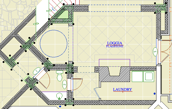
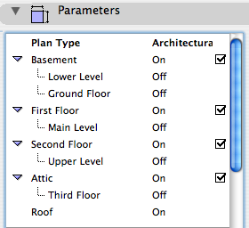
It knows what kind of plans we usually have. (Architectural, RCP, Electrical, etc.) It knows roughly what stories we use. You tell it what kind of plan it is (it can be custom), and what stories you have, and what the stories are called. It places the appropriate titles on each story.

In the templates, there is one of these guys for each plan. In setting up the project, you need to set up the plan titles. For example, turn the attic off if there's no attic. The best way to do this is all at once: Turn all the note layers on, select all the title objects, and change their story setup.

The different names for a given story are all hooked together, so if you turn 'Main Level' on, 'First Floor' will switch off.

Place the object on the lowest story that is in use. If that's the basement, turn 'Basement' on. If not, turn it off and 'First Floor' will take its place. Etc.

After some experimentation, this is the best method I can find for using external, standard details. It definitely has room for improvement. The biggest improvement would be for AC to allow detail markers to reference external drawings. It's a huge hole in the program that has to be fixed. In the meantime this isn't too bad.

The executive summary: Copy details from projects and clean up their layers and other attributes. Place the details in a central PLN file, one per story. Or, draw them from scratch in the central PLN. Publish modules of the details. Hotlink or merge the modules into detail windows of running projects, and use detail markers to refer to them normally.

In this example I'm talking about the wall and other assembly types. It could used for any standard details you would like to share. Also, we will use this as a standard method beginning with AC10. In the meantime, everything here which concerns placing detail modules can be applied to current assembly modules at 3 Resources / Modules / Assembly Types.

More»