Why: Same reason as always. Model views are more consistent and easier to maintain. Modeling is the better way to work things out for real. You can block up passable wall sections earlier without sacrificing consistency. To get them graphically perfect will require conversion to drawing in the end, but you can put it off at least through design development.
How: Lots of 2D fills, lines, and objects placed over empty model elements. You were going to use all that 2D stuff anyway. A lot of the fill-placement is to make up for the fact that composites can't be scale sensitive yet.
Very high quality cleanup is required. Ceiling finishes (drywall, wood) need to be modeled. For these there's a new layer, F Clg Fin. Only model them where they are cut by the wall sections, not everywhere.
Fills that need to be added include plywood, drywall, finish wood. The ceiling finished may be modeled with the desired output fill, since the elements don't show in the building sections. One less fill to draw.
The layer combination is the same as A2 Section/Elevation except:
L Grade is hidden.
F Clg Fin is showing.
The display options set is the same as A1/A2 except:
Fill Background Color: Transparent
(These are easy changes to make in running projects. I haven't gotten around to updating the templates, but I will soon, and then I will strike this sentence.)
Naturally, you will need to save views of your windows with these settings.
Some objects (Crown Tool JAM9) have custom section fill settings for wall section scales. Note, there is a bug that causes custom fills to break when objects are targets of SEO subtractions.
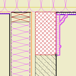
Because of the "Transparent" setting of fill backgrounds, masking fills with a background don't work. 'Solid Fill' with pen 91 (or other white-printing pen) should be used for masking. If a fill pattern is needed, you must place two fills; Solid to mask, and another for the pattern itself. Make sure to bring the pattern fill in front of the mask fill.
For example, in this image, the stone veneer is modeled, and the concrete block behind the frieze board is made of two fills.

This image also shows a limitation of this this method. There are heavy lines on the interior, such as at the top of the top plate, which you can only fix by converting to drawing. Someday, maybe, Archicad will be able to tell the difference between a cut edge that meets air and one that meets another cut edge.
This method provides a good example of working at the limits of Archicad, finding workarounds, and wishing for improvements. The tools work well enough to use the basic model geometry as a base for the annotated drawing. Features of GDL allow objects to have some behaviors (scale-sensitive section fills) that regular tools lack. We have to use all-empty composites and add fills, while wishing for true scale sensitive composites, and proper composite cleanup in section. We have to live with heavy lines inside details for a while, while wishing for that cleanup condition to be handled better.
