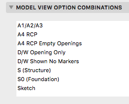
Beginning with Archicad 20, the fills division of Model View Options is obsolete and fills are handled by Graphic Overrides. This enables us to eliminate several combinations that were needed in Archicad 19.

The MVO dialog has five divisions. But it's really only four once you check the box to get rid of the Fills division, now that you know fills are handled by Graphic Overrides. And for us it's only three, because Floor Plan Detail Level of Door Window and Skylight Symbols doesn't apply to our library parts. That leaves:
Options for Construction Elements, concerning the display of real things, including openings, columns, beams, and markers.
Miscellaneous Settings For Library Parts, where the only setting used by our library is 'Lamps and HVAC Floor Plan Symbols', FKA 'Story Viewpoint Type', which controls the display of certain objects in reflected ceiling plan.
Options For Rill Libraries, which is our custom panel that handles a couple of display issues that can't be addressed in other ways.
The keyboard shortcut to open the dialog is Cmd+9. I think the MVO dialog is pretty good about previewing the effects of most of the controls.
Rather than describe each combination, or heaven forbid build a table, I'll describe the A1/A2/A3 combination, then how the others differ.
A1/A2/A3 is for plans, sections, elevations, wall sections, interior elevations, and details. It is also the combination for general work. Beams are Contour Lines (no reference lines). Doors, Windows, and Skylights Show on Plans, with Markers. Column Symbols Show (though we don't use them). Curtain Walls are Full (though we rarely use them). Zone stamps show.
The Lamps and HVAC Floor Plan Symbols are 'Realistic'. (This is not the right word for it; the old 'Floor Plan' was better for our purposes) This will only change for the RCP.
We used to have Working Plan and Model combinations, where the beam reference lines showed. In recent versions of Archicad, it is possible to detect the beam reference line without it being shown, and this is sufficient for typical use.
There are two combinations for reflected ceiling plans. One way to handle openings in RCP is to Show Opening Only, with Contours, and this was our only way until recently. A4 RCP Empty Openings does this. The other combination, A4 RCP, uses an alternate plan symbol in combination with that floor plan/RCP switch. It is described in detail here. The default in the template is to use the new symbol method, but you can switch the RCP views to use the old one if the need arises. The key is that only our doors and windows will respond correctly to the floor plan/RCP switch.
D/W Opening Only Doors and Windows are Opening Only, with contours. Skylights are shown normally. It's used for mechanical, plumbing, and site plans. You will only see the effect of this combination on the site plan if you choose to show the building's walls, which is not the default. (The building is usually shown with a 3D top view.)
D/W Shown No Markers Openings are shown, without markers. This is the only difference with A1/A2/A3. It's used for electrical plans, as well as background and binder plans, where the cut fills are handled by graphic overrides. Previously, this combination was named after the plan types that use it, but that name was awkward
S (Structure) is for framing plans. Doors, Windows, and Skylights are Opening Only. Under Options for Rill Libraries, the two options for posts are both checked. (The option about labels on posts in deprecated as of Archicad 19. Posts should be labeled normally using the label Description JM19. If you're in the future and you don't see the label option, I took it out at some point.) In all other combinations, those options are unchecked.
S0 Foundation is for the foundation plan. All openings are hidden. There are cases where you might want to show the openings, using Opening Only. You can either modify this combination or reassign the Foundation Plan view to the S (Structure) combination.
Sketch is only used for sketch renderings. Under the Rill Options, 'Linify thin parts' makes certain library parts such as balusters and windows draw thin parts with a line rather than a skinny solid shape. This reduces the number of redundant lines in the rendering, making those parts less splotchy.
If you rename an MVO combination, any views that were using it will say the combination is 'Missing', but the actual settings will not change. View settings need to be updated manually. If you delete an MVO combination, which you never should, views that use it will start using the next combination in the list, giving very unpredictable and definitely wrong results.
