This is a new approach to showing openings in reflected ceiling plans, using a modified plan symbol rather than an blank opening. I haven't put it in the template yet, and it may not be required or appropriate for every project, but it is better overall. The biggest limitation is that in order to use it you have to use our doors and windows almost exclusively. This doesn't bother me much.
Model View Options for RCP
Archicad offers the ability for library parts to change their appearance when they are shown in a RCP as opposed to an ordinary floor plan. The user-facing part of this is an setting within Model View Options:
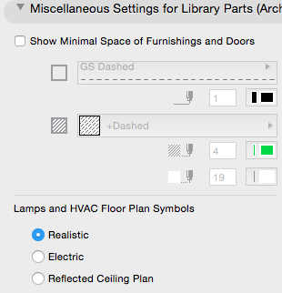
When this setting was born long ago, there were only two choices, for floor plan and RCP. Now there are three, but I'm ignoring the 'Electric' one. I'm also ignoring the implication that the switch only applies only to lamps and HVAC objects. For our purposes, 'Realistic' corresponds to the floor plan.
Save the appropriate setting with the floor plan and RCP MVO combinations, and you have two kinds of output from one library part - yay unity.
The internal part of this feature is a GDL request, "floor_plan_option". Library parts that use this request can respond to the state of that MVO switch.
The Ceiling Switch
The simplest object we have with this feature is Ceiling Line JM11. It draws a line that changes its line type depending on the kind of plan. It is most often used in attics for hips or clip lines where the ceiling meets the roof. (Showing roofs and slabs on the story below rarely works out for plan graphic standards.) The geometry of the object doesn't change - it's a line. Only the pen and line type attributes change:
!! Request state of ceiling switch
rr=REQUEST("floor_plan_option","", storyViewpointType)
IF storyViewpointType=1 THEN !! ceiling
    PEN rcpPen
    LINE_TYPE rcpLT
ELSE      !! floor plan
    PEN planPen
    LINE_TYPE planLT
ENDIF

!! Draw line

LINE2 0, 0, A, 0
Using a line is never my first choice, and using an object for a line is awkward because intersect doesn't work and stretch is weird. And it's not a polyline is it. But I prefer one object to two lines on different layers. There is also an accessory version for outlining holes in ceiling slabs. Elements which should appear in plan and RCP belong on the layer A Ceiling All.
Note that this switch only works for library parts. We should all actively wish for RCP attributes for general tools.
Cover Fills on the Ceiling
We also use the RCP switch in the Crown Tool. For closed shapes (coffer, triangles, etc.), we have the option of a cover fill in RCP mode only. This would represent beaded board, e.g., surrounded by the moulding. In this object, there is a whole section of the 2D script that only runs for the RCP case.
N.B: Ceiling moldings that you want to see in RCP belong on F Trim Crown. To hide them in RCP, use F Trim Int/Ext Hi.
Ceiling Panel Objects
To place a horizontal panel in a soffit, we use the object Trim Panel Ceiling JM16. It is set in the bottom of a slab with a subtract-down SEO. Of course we want to see the panel in RCP, so it goes on F Trim Crown.
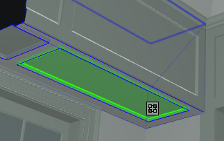
Here's a patch of old RCP:
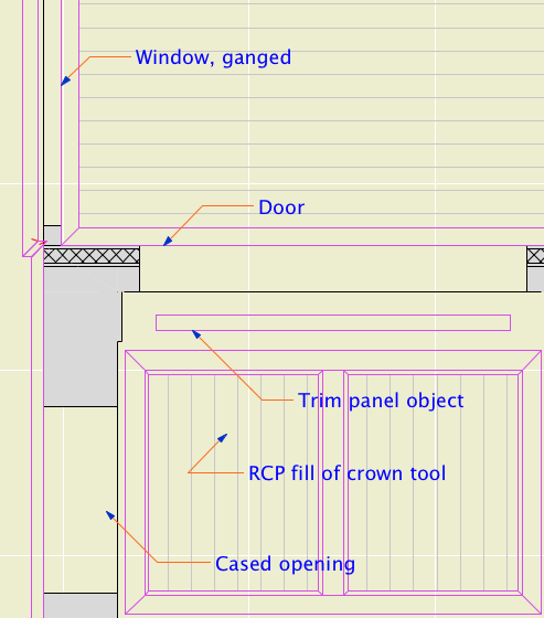
Moldings and a ceiling panel with the old RCP view options.
Ceilings of Openings
Until now we have displayed doors and windows in RCP with the model view option 'Show Opening Only', 'with Contours'. This shows a blank space in the wall with no detail. In GDL terms, the 2D script does not run at all with this option. The script only runs for 'Show on Plans'.
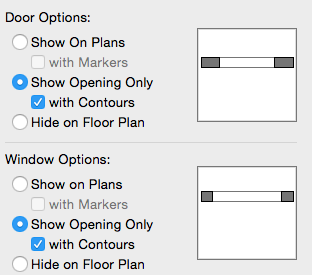
Show opening only, the old RCP setting
When a cased opening is placed in a very thick wall, we will often put panels in the jambs and head of the opening. The panel in the head is exactly like the soffit panel described above.
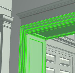
With the blank openings of the old RCP, we now have an inconsistency: Panels in soffit slabs are shown in RCP, while panels in the heads of doors are not. It is an axiom of graphics that similar things must be shown similarly. Otherwise, good luck getting the contractors to believe that the cased opening panels were 'in the project'.
We need an alternate symbol to show the opening panel in RCP. Then we can 'Show on Plans' and use the ceiling switch to hide the normal symbol and show the panel. For openings without a panel, there is a simplified symbol that looks a lot like 'Show Opening Only'.
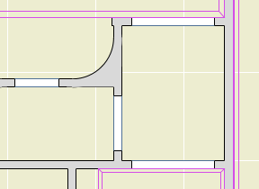
If Openings Have RCP Symbols...
We might consider other ways to improve these symbols, since we have now script control over them.
• The floor plan symbols show the masonry opening, while 'Show Opening Only' does not. The RCP symbol can show it.
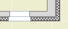
• For ganged windows, we place multiple units as a single window element with a single schedule tag. While 'Show Opening Only' wipes out the mulls, the RCP symbol can show them.

These are both minor issues, but they improve general consistency a little.
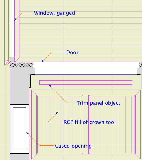
Proper panel in the cased opening, ganged windows, masonry opening
No Half Measures
It certainly is good to be able to show that opening panel. But there is a catch. 'Show on Plans' applies to all doors and all windows. (The settings are separate but we keep them in sync.) You can't 'Show on Plans' for some openings and 'Show Opening Only' for others. That means all the doors and windows in the plans must have an alternate RCP symbol in their 2D scripts.
So I went ahead and did that. But the Archicad library doesn't support this, and I don't think many others do either. If you use an Archicad door with the new MVO setup, it will show a swing, while the other doors don't, and that's graphically incorrect without possibility of parole.
This is one of the advantages of maintaining our own libraries. In many cases we can grant our own wishes.
I can think of two workarounds if you have a couple of AC library openings:
• A patch on the RCP Note layer.
• Save a copy of the AC library part, and put the ceiling switch code in the 2D script. Such a part should be placed in the embedded library.
If you are using a lot of AC opening parts, then we have a problem with our library we need to address. That's the point of having an insanely custom library.
