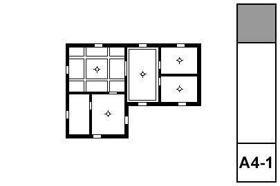
What shows:
• Walls
• Ceiling trim and finishes
• Ceiling fixtures including lights, fans, and mechanical fixtures
• Floor elements, including deck edges, stairs, counters
Using graphic override rules, floor elements are automatically shown dashed in RCP. And, ceiling elements, which are drawn dashed in the floor plan, are automatically shown solid. What a time to be alive.
(Yes, I copied and pasted this directly from the electrical plan post.)
The RCP shows everything on the ceiling, whether electrical or not. This includes trim, ceiling finishes, and HVAC registers. The electrical plan shows everything electrical, whether on the ceiling or not.
The plans should be separate if combining all that stuff would make a confusing drawing. If the combined drawing would not be too much of a mess, the two drawings can be unified as the RCP and the electrical plan can be discarded.
Our principals have the habit of red-lining electrical work on the RCP either way. Don't let this distract you from the right decision about using separate plans, or not.
• Door and Windows: A4 RCP shows a special version of the symbol. A4 RCP Empty Openings shows just the opening. The former is preferred, and I think I have all the doors and windows responding correctly, but there may be quirks. Essentially, this is an alternative door/window symbol only for RCP, which we can do because...
• The 'Ceiling Plan' switch is on.
Seriously. You have to draw eave edges with a polyline, that's just life sometimes. But: Use the dashed line type and the layer A Ceiling2. Just like countertops and beams, graphic overrides make it just work.
Special ceiling finishes, such as beaded board, should be drawn with fills. (If you are using the crown tool in coffer mode, the object can automatically show a ceiling fill. Check under the Plan settings.)
You also need to draw any paneling that isn't modeled, and any other fine ceiling detail.
All this stuff goes on +A RCP Line.
Annotations go on +A RCP Note.
Like any drawing, call out what needs to be called out. If there are important alignments in the ceiling involving fixtures, paneling, trim, etc., those should be dimensioned or otherwise noted.
It's sometimes helpful to note ceiling heights where they vary. For this you would use a level dimension with manual text. I have a label for dimensioning slab elevations, Slab Elev, but it's a bit awkward to use in RCP because the labeled slab has to be visible in order to see the label (LAME). In the project where I used this method, I made a new layer, A Clg RCP, for ceiling slabs that need to show in RCP. I don't know if that's worth it or not. Labels need a lot of work.
You can call out crown objects directly using General Element Label JM20 with the Moulding Object option.
