On Land

Environment Information
At Rill Architects we run ArchiCAD on macOS. If you work at Rill, this is your stuff. If you don't, but you work in ArchiCAD, you may find something interesting. Anybody else, I don't know.
RSS
Documentation Archive

All Entries | 1 | 2 | 3 | 4 | Older »

Here is a method for keynotes in vanilla Archicad, except it doesn't work. It takes a classification, three properties, an object, and a schedule:

A classification called Keynote.

A property called Full Keynote, string type option set. Each option consists of the short note, a separator, and the long note. The separator can be anything that doesn't occur in content, such as "::". The short note is displayed in the view, as an object. The long note is shown alongside the short note in a schedule.

A property called Short Note, string type, using the expression SPLIT (Full Keynote, "::", 1). This property will output the short note part of the Full Keynote property.

A property called Long Note, string type, using the expression SPLIT (Full Keynote, "::", 2). This property will output the long note part of the Full Keynote property.

All three properties are available to the Keynote classification.

An object, maybe called Keynote Object, which acts like a label, with text and a leader. The text is the Short Note property. The objects are classified as Keynote.

A schedule of the Keynote Objects, which shows columns for the Short Note and Long Note properties.

The format of the Full Keynote options is:
Note 1::Full text for note 1
Note 2::Full text for note 2
Note 3::Full text for note 3
etc.
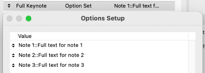
Keynote Options

Options are created as needed in the Property Manager. The user places Keynote Objects and selects the desired Full Keynote property option.

Keynote Options

The object displays the short text...
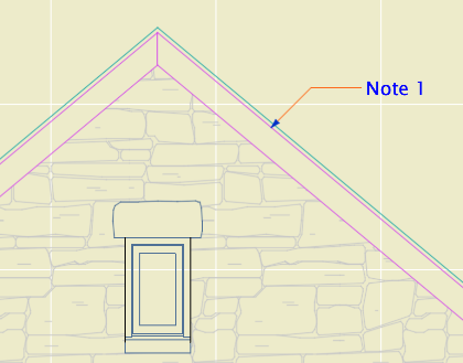
Keynote in View

...and the schedule lists all the notes.

Keynote Schedule

The only catch is that only floor plan elements can be scheduled; the workaround for this is to make sure any elevation keynotes are duplicated on a hidden layer in the plan.

This is super simple once you get your GDL friend to write you the object. No new tool, no add-on.

But it doesn't work due to limitations in Archicad. Only labels can display properties, and of course they display the properties of other elements and have no properties of their own. And labels can't be scheduled. Objects can't display properties, not even properties attached to themselves.

I expect Graphisoft finds the notion of attaching properties to annotations rather than building elements to be Not BIM. Respectfully, they need to get over it. (Or let us schedule labels, which I guess also Just Seems Weird.) This is an old, constant, high-ranking user wish, especially in the USA, and it is THIS CLOSE to being crossed off.

Allow objects to display text of their own properties, and we're done.

This object is a tool for removing slope distortion from angled details such as rakes. A big improvement over this.

More»

This is the current state of element schedules. All projects will have schedules for windows, interior doors, and exterior doors. Many projects will have finish schedules, which are schedules of zones.

Let's quickly review the basics of interactive schedules. In the scheme settings, there are criteria, which determine what elements will be listed, and fields, which are the information to be shown about each element. Schemes can be imported and exported as XML files.

Then there is the schedule itself, where you control the column widths, header content, and text settings. It is pretty WYSIWYG with respect to output.

In addition to making schedule output, schedules can be used to inspect and edit model information. More on that later.

More»

In Archicad 21 you can use autotexts in labels. Rather than describing an element in disconnected words, you can display the actual properties, attributes, dimensions, etc. of the element. Use Archicad properties and name your building materials, surfaces, and composites carefully, and you can get good automatic notes. GDL-scripted labels have long been able to do this, but it's an order of magnitude more convenient to have this built into the basic text label.

Generally, such associated annotations are better, because if anything changes in the elements the annotations change too. Think ordinary dimensions. An element and its associated annotations are one thing.

But my goodness they botched this for US users.

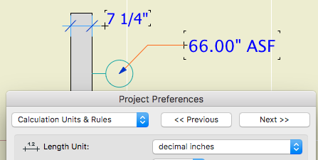
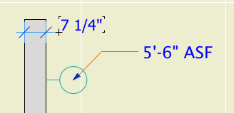
If you use (feet and) fractional inches for your dimension units, you can't use any dimensional autotexts in labels without looking like a hack. This is because autotext dimensions are formatted according to the calculation units preference rather than the dimension units. There are no fractional length unit options in the calculation units preferences.

Here are two simple dimension values. The wall thickness is a dimension and the fixture elevation is a label autotext. Archicad says with a straight face that one of them is a dimension and the other is a calculation. A calculation with no operators and a single term, apparently.

calculation
Doesn't everybody vary units within drawings? No, no one does.

Wait, here's a label that works.

This is the Archicad library's Elevation Label 21, a scripted label (no autotext) that has been available for years. (Like a lot of Archicad library parts, this label over-serves and you have to fiddle a lot to get it looking right, but it's functional and reliable.)

dimension
That's not so hard, is it?

This label is scripted to use the dimension units, as common sense would dictate. There are global variables for the calculation units too, so they could have this label use them, but it's not even an option, because that would be (is) ridiculous. If I wanted decimal units, I could just set the dimension standard that way.

Maybe in Archicad 22 they'll fix the Elevation Label to use the calculation units for consistency. (KIDDING!)

I don't know how this decision made it out of committee, and I'm sorry I didn't notice it earlier, but that usually doesn't matter. This is worse than How Could This Possibly Be What I Want, it's just carelessness that never got reviewed because it doesn't affect metric users. (But it's wrong there too.)

Why don't I care about the reason?

Because I'm a user, not a developer. My job is to make my projects work, and the developers job is to make the program work. I'm sure there's a reason for this situation, and it might be very interesting from a development point of view, but that's not my point of view. To a user, it's just wrong and needs to be fixed. (In all honesty, as an Archicad observer I'm curious about the reason, but it's not the user's role to care.)

And, the whole dimension and calculation units thing probably needs a do-over. It would be welcome to have units control at the level of the element (dimension, label) or schedule. An electrician might prefer that fixture elevation in fractional inches, for instance. This will become more important as more annotations become automatic.

PS, metric people: Sure sure, I'm with you but you're not helping.

This clever trick from Patrick May at 4dProof about labeling zones in section has two parts. The clever part is the lateral thinking of labeling things in the zones rather than the zone itself. The other part is the introduction of autotexts in labels in Archicad 21.

The lateral thinking part could have been discovered versions ago, you just needed to script the label in GDL because there was no label autotext.

So when I got done slapping my forehead I wrote a label in Archicad 20 which matches our zone stamp and the object we have been using to 'label' rooms in section. And while the label autotext is very handy, but, as always, GDL gives you more power and control.

First, let's review the clever trick. You can't label, or even detect, zones in section or elevation. What you can do is label a model element, and have the label state what zone an element is in. (Related zone condition is determined in plan. The elevation of elements and the height of zones doesn't matter.) Turn the pointer off, and you have a word which is the name of the room floating in the room. The label is live data - if you rename the zone, the section labels will be updated. And, you don't need to know the name of the room to label it.

These element types can report their related zone:
• Object
• Lamp
• Morph
• Beam
• Column
• Stair
• Wall, if zone boundary, with caveats

These element types are ineligible:
• Slab
• Roof
• Shell
• Wall, within zone
• Door
• Window
• Skylight
• Railing (AC21)

To label the room, you need to find an eligible element in it. In our projects, considering that not every room needs to be labeled, almost every room has a lamp, object (moulding, appliance, plumbing fixture, etc), or beam in it. If there are none of these in a room, I suspect the project isn't far enough along to be labeling rooms in section.

The main walls of the room, since they are usually boundary walls, are a good choice with caveats. There may be two (or more) zones related to the wall, so you need to be sure the right one is shown. In Archicad 20, sometimes there are two zones available and the label just ignores one of them. (This seems to be fixed in Archicad 21.) If the walls won't cooperate, you'll need to find something else to label.

Room names in section

The basics described so far also apply to labeling with autotext in Archicad 21. These are the additional features of this scripted label:

It precisely matches our standard for room names, including the fussy underline and the ability to 'stack' two-word names.

It can show the name and the number or both, and the font and size of these texts can be different.

It tries to help if you label something ineligible. If you label an ineligible element, there is no text to display. In this case the autotext label just sits there, blank and invisible. Go ahead, place a bunch of empty labels until you notice the pattern! The scripted label helpfully states 'something is wrong' in this case. (The two things that can be wrong are that the element is of an ineligible type, or it is not inside a zone. GDL doesn't offer the ability to tell these conditions apart, otherwise I would have the label tell you.)

If you are labeling zone boundary walls, you can switch between the two zones the label knows about. (Autotext only offers one zone and no way to switch that I can see.) There is a checkbox in settings for using the 'other' zone, and even better there is a graphical switch at the top of the text block. (It only appears for walls with zone zones.) Switching doesn't always help: Since walls can bound more than two zones, the one you want might not be offered. You'll need to label something else.

Update, July 7, 2017
Only the main properties (name, number, etc) of the zone are available to labels. Our zone stamp has additional parameters, such as an optional short name which can be shown in small rooms. These parameters aren't available to the label, so you can't use the short name for rooms that are small in section. In that case you can make the text size smaller or use the number instead.

I have tweaked the label so it behaves more civilized in the settings dialog.

Download

Graphic overrides greatly expand the number of ways an element can represent itself in different kinds of documentation. This means less redundant 'drawing', and more unity.

The RCP has long been a frustrating form of output if you're trying to minimize drawing. All the things that need to be shown are modeled, but Archicad has had limited facility to present these elements with properly modified attributes. In practice, 'properly modified' usually just means a dashed line type.

Now, with graphic overrides, we can choose any kind of element and say, draw it with a dashed line type instead of solid.

It follows from this that we probably need fewer custom object solutions that use the ceiling switch.

More»

Graphic overrides are a new feature of Archicad 20. They allow you to choose elements by criteria, and change their appearance attributes. The changes are grouped into combinations which can be saved with views.

Here's how to use Archicad: Build a model, and try to create all the documentation while doing the least amount of non-modeling. If you find yourself drawing something that you have already modeled, it must be because the thing can't be made to present itself in the appropriate way for your documentation. Archicad has always offered methods to help with this. A door can have a complex plan symbol, a simple symbol, or just an opening; it can have a schedule marker or not; or it can be hidden entirely. The same one door appears in 3D and in a schedule. One door, many appearances in documentation. This is unity.

Graphic overrides greatly expand the variety of ways that a single element can be presented. This means it is less likely that you will need to 'draw' an element you have modeled in order to get it to appear correctly in your documentation.

This feature gets at the heart of what Archicad is all about. It will definitely change a lot of working and documentation methods. If it doesn't, you are probably using Archicad wrong.

Since this is a major feature, it is impossible at this early stage to predict everything that will change. But I am getting a sense of what the categories of changes might be.

More»

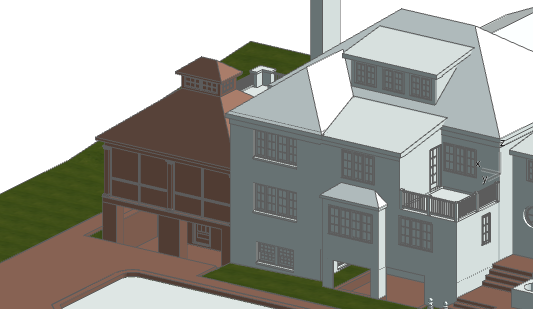
Here is a massing model showing existing conditions and a proposed addition. It is mostly done with renovation filters, with a couple of tweaks from graphic overrides.

existing-new massing model

Existing is overridden with one surface, the light color in the picture. If you are OK with existing elements not having fills in elevation, you can leave this override on. If you want the fills in elevation, you need to turn the surface override off, and switch it back and forth manually. This setting can't be saved with views or filters. We really need per-filter renovation overrides.

New is overridden with a different surface, the red in the picture. New elements are generally shown, not overridden. So the surface override can be left on. It is currently the only active override setting for New.

There is a new renovation filter, 07 Massing by Status. Existing=override, Demo=hide, New=override. Again, in all other filters, New is shown.

These are the graphic override rules:

Site Green finds 3D elements (in practice, they are meshes with the occasional slab) on the layer C Site3, and changes their uncut surfaces to 'Grass - Green'. Graphic overrides happen after renovation overrides, so while the site has existing status, it is not shown with the white color.

3D Lines Match finds All Types of elements, and changes their Line Pen to a medium gray pen. (It's our pen 137 in the picture, the default pen 2 would be fine too.)

Glass can't be overridden within windows and doors. (This would require attribute-level graphic overrides.) If you want clear openings of any sort, you have two options I can think of:

One way is to use 'Filter and Cut Elements in 3D' to hide the doors and windows. This will give completely empty openings.

The other is to use a graphic override rule similar to the site/grass rule, where doors and windows are chosen to be overridden by a clear surface. But, all parts of the doors and windows will be clear, not just the glass.

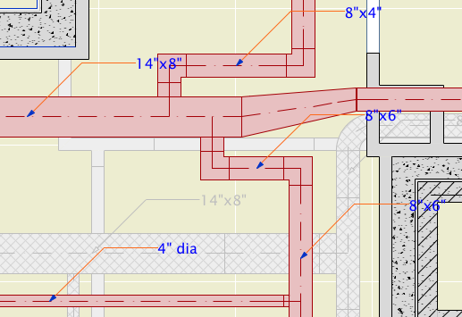
This is a very simple label for duct elements made with the MEP Modeler add-on. It's intended for use with any simple duct type, including Straight, Bend, Take-off, and the Obstruction Fittings (as far as I can tell). I'm using it solely for straight pieces, since no one is fabricating anything from my plans - I just want to coordinate with the HVAC engineer.

For round ducts, the label reads '5" dia'. For rectangular ducts, it reads 'Width x Depth'.

All our ducts are sized in inches, so I'm using a fractional inch format for the dimensions. On the off chance that someone else might find this label useful, I've added a parameter so you can choose to have the label's format match the current dimensions format in the project preferences.

It was convenient to use Select All for the (straight) Duct Tool, then label them all with the Label Selected Elements command (Document -> Document Extras).

Duct Labels

Download

Until now we have done the electrical symbol legend as a hotlinked module of a story, where the lamp and object elements are placed in the floor plan within a table drawn with lines. This is a static resource, unless you break the module hotlink and modify it.

It is possible to create the legend using Interactive Schedule. The advantage of this is that it will only display the symbols that are actually in use. This makes a more compact, relevant, and readable table.

Electrical Symbol Schedule

The schedule itself is very simple. It only shows two columns. The first is the 2D symbol, which is a field/parameter of objects and lamps. The second is a custom parameter of our lighting and electrical objects - the parameter is 'desc' internally, and is called 'Type' in the settings. (A missing feature in most library parts is an ordinary name that can be easily listed and labeled. The object name usually doesn't work, and style options usually go by cryptic handles such as 'Style 1'.)

From here on I will say 'object' while I mean 'object or lamp'.

The schedule merges identical items into one. Remember that the IS only considers displayed information when deciding what is identical. So if the symbol and Type are the same, none of the other parameters matter - you will only get one entry. You have a surface fixture at 8'-0" and one at 9'-0"; they are the same to the schedule.

Simpler objects know what they are out of the box. Ceiling fan, duh. Some objects have options which change their identity. A recessed fixture can be ordinary, waterproof, a heat lamp, adjustable, etc. A smoke detector can be a CO detector, or a combination. The Type parameter should automatically respond to these details. The schedule will list separate items for each of these differences, because the Type field is different. The symbols will be appropriate for each difference.

The electrical switch object will always present itself as a pair of switches, one regular and one dimmer. This is so sets of two, three, four, etc. switches don't show up as separate items. GFCI switches are shown separately. (GDL folks: This is done by drawing a specific case of the symbol when the GLOB_CONTEXT is a schedule. In the future, but starting now, GLOB_CONTEXT is deprecated and you should use GLOB_VIEW_TYPE=9 (Calculation) instead. Since I'm still maintaining our AC18 Library, I can't implement this change yet.)

I had to replace the ceiling fan symbol so it would fit in the same cell height as the others.

Again, when you have your own library, you can do whatever you want.

Criteria
Electrical Schedule Criteria

The criteria look more complicated than they are. It's just:

• Objects and Lamps

• On any electrical fixture layer

• But not on the Footings story, because that's where the old legend is placed

• And not part of a hotlinked module. Delete this criterion if the module is not covered by a separate project, and you want to schedule the module's fixtures.

Fields
Electrical Schedule Fields

The fields are only two, as described above. The 2D symbol and the Type:

The schedule is saved as a view in the Schedules folder, alongside the window and door schedules. It should be placed as a drawing on each electrical sheet.

This is a new approach to showing openings in reflected ceiling plans, using a modified plan symbol rather than an blank opening. I haven't put it in the template yet, and it may not be required or appropriate for every project, but it is better overall. The biggest limitation is that in order to use it you have to use our doors and windows almost exclusively. This doesn't bother me much.

More»

Short Name
So that a zone can be shown with an abbreviation in the plan where there's not enough space, and with the full name in schedules where abbreviations look awkward.

Put the abbreviation in the Short Name parameter. If the parameter is empty, the full name is used in plan.

Another idea would be to hard-code standard abbreviations for typical room names.

All Entries | 1 | 2 | 3 | 4 | Older »