On Land

Environment Information
At Rill & Decker Architects we run ArchiCAD on Mac OS X. If you work at Rill & Decker, this is your stuff. If you don't, but you work in ArchiCAD, you may find something interesting. Anybody else, I don't know.
RSS
Template Update Archive

All Entries | 1 | 2 | 3

Automatic titles are not new to 10, but title objects are new, and now that they are objects, we can use them, which is new.

A drawing title is essentially a marker for a drawing element. Like section markers, detail markers, symbol labels, and door/window markers, you choose the title from a popup menu rather than from an object-type browser.
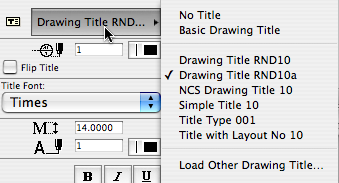
Drawing title list

As with all markers, there's no way to restrict the list. It shows all the loaded drawing titles, and it's up to you to pick the right one.

Elevations, sections, site plans, and details should all use automatic titles. Plans are the only drawing which has an object (Plan Title RND10) in the window. PDFs placed for notes ordinarily shouldn't have a title. Scanned details might, it depends.

Since the title and its settings are part of the drawing element's settings, you can change them in groups using the Drawing Manager. (Note: You must have a layout as the frontmost window to do this; otherwise the title tab is grayed out.)

Drawing Title RND10a is very similar to Drawing Title RND9a. There's a couple of 10-specific changes:

• By default, the title uses the name of the drawing (which should come from the name of the view, which should come from the name of the window). You can put in a custom text under the 'Title' tab in the drawing settings dialog.

• Titles don't have a length parameter like a regular object. So the Length parameter controls the length. You would normally adjust this graphically:

Title stretch

The length still has a minimum equal to the title text length.

Again I have to apologize for issuing a '10a' revision. There was one issue with Drawing Title RND10 that I couldn't fix in place. That title would appear right on the corner by default. The new one appears 3/8" below the corner, which makes it easier to move the title as needed. Note the 'move marker' palette button:
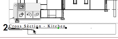
Drawing drag

And, full disclosure, I broke the minimum length thing, but now that's fixed.

The templates have a fax transmittal as part of the layout book.

More»

There are the layer combinations for work and the layer combinations for output. In the past, the output LCs have had all their layers locked. The only reason for this was make clear to the user that they're not in a working combination. Not a critical point but there it is.

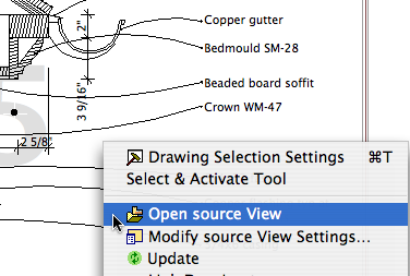
Now there's a stronger reason to have the layers unlocked in output LCs. In AC10, you can right-click on a drawing and choose 'Open source View' to, right, open the source view. (In AC/PM9, this command existed but it never worked as far as I could tell.)

Open Source View
If you are viewing a drawing and see something that needs fixing, you can open the view and get right to it. So the layer locking should get out of the way.

In the architectural LCs, all the visible layers are unlocked. In the specialized plans (electrical, e.g.), only the special layers are unlocked.

In the templates for 10, I've modified the layer combinations as suggested here. There's a couple of tweaks since then.

Changing the LCs is a minor change compared to changing the layers themselves, which can be very perilous. (There are a couple of layer changes in the new templates. Just a little peril!)

In this theory of layer combinations, there are three main types, and then a couple oddballs. The three:

Output. Used by publication views.

Working. Where you spend most of your time.

Special Tasks. Unusual LCs for doing a certain task once in a while. E.g., Site cutting, building stretching, elevations with just notes.

The new LC arrangement makes these categories clearer. The working LCs begin with numbers. The output LCs begin with the letter of their sheets. The specials begin with x. The oddballs: The binder LCs begin with z. Since they're not used until the very end, they have to be last. 'zzz All' is sort of administrative, and you never use it in real life.

I've tried to make the purpose of each LC self-evident in the name.

Here's the list. (Existing/addition-only LCs are indicated by '*'.)

  • ! Ex1 Existing Plan*
  • ! Ex2 Existing Elev*
  • ! Working Existing Model*
  • ! Working Existing Plan*
  • 0 Working Model
  • 1 Working Floor+Roof Plan
  • 2 Working Elev+Sect+Detail
  • 3 Working Wall Section
  • 4 Working RCP
  • 5 Working Interiors
  • 6 Working Site 120
  • 6 Working Site 240
  •  
  • A1 Floor+Roof Plan
  • A2/3 Elev+Sect+Detail
  • A3 Wall Section
  • A4 RCP
  • A5 Interior Elevs
  • A5 Enlarged Plan
  • C1 Site Plan 120
  • C1 Site Plan 240
  • D1 Demo Plan*
  • E1 Elec Plan
  • F1 Furniture Plan
  • M1 Mechanical Plan
  • P1 Plumbing Plan
  • S0 Foundation Plan
  • S1 Structure Plan
  • S2 Structure Model
  • S3 Structure Wall Mask
  • View 3D
  • View LW Render
  •  
  • x Background Plan
  • x Elevation Notes
  • x Gross Area
  • x Object Lab
  • x Shoot RCP
  • x Shoot Roof Plan
  • x Site Cutting
  • x Stretch House
  • x View Chimney
  • x View Flues
  • x Working Dims Plan
  • x Working Trim
  • x Zones
  • z Binder Elevation
  • z Binder Plan
  • z Existing Binder Elevation*
  • z Existing Binder Plan*
  • zzz All

The current standard for library loading is to load only the folder specific to the project. That is, don't load the entire 2 Project LIB 9 folder. I updated the templates so that the only libraries loaded by default are 1 Rill & Decker LIB 9 and AC9 Library Special Edition.

When the time comes that you need project specific objects, create a folder in 2 Project LIB 9 with a name like Projectname LIB.

When the project is completed and moved to Past Projects, the project library should be moved to 2 Libraries / Other LIBs / Past Project LIBs.

If you know of an object in a project library that you could use, ask the person who made it to move it into the standard library. Or, remember that you can load objects individually.

The idea is to not load objects that you will never use, such as other people's patches.

To facilitate the creation of post-project binders.

More»

This layer is for operator elements which you would like to show in plan.

Example: You can use the filleted disc and box objects to cut a ceiling, and display those cutting elements in the plan with a dashed line. You still have to draw them over in the RCP, but two elements is better than three.

Another example: A slab subtracted from a wall to make a niche.

I've added an 'Alternates' folder to zTemplate folder, in 1 Design. It should have been there before, sorry.

It gives me an opportunity to discuss alternate handling, or at least to give you one case study. Vassos, although it's under construction, has occasional lapses into design development. The clients were interested in seeing alternatives for one part of an elevation. We offered two, which forked into three.

I saved a copy of the project for each alternate, with a descriptive name, in that Alternates folder. I developed the model for each alternate. We wanted to present a perspective and an elevation for each choice. Since the alternates are in separate files, and all the alternates are separate from the main PLN, it's easy to simply use the views you already have. You can't mess anything up.

To present the choices, I created a new subset in the main layout book. There's no reason to create separate 'books for each. Within the new folder, there are two layouts for each alternate. I hooked the new layouts to the 11x17 Master. Then I imported the perspective and elevation views from each PLN.

Once the decision had been made about which version to use, it was time to begin treating that scheme as the real project. I renamed the main PLN, which had been untouched, with a date, and moved it to the '6 Old Files' folder. I saved-as the anointed alternate with the original name of the main PLN, at the top of the project folder. This means the layout book never knows anything happened. If you change the name of the project, you will need to re-link your views.

In the end, we have three alternate PLNs set aside, the pre-alternate version of the project intact, and the layout book not disrupted. And a compact record of the alternates' presentation. Pretty good.

In this case I was fortunate that, since the project was 'done', there was no other work going on anywhere. Presenting alternates in the DD phase is trickier, especially if the design decision is slow in coming. If you need to keep the main project moving while the alternates are being developed, it is better to merge the chosen alternate elements back into the main project.

This isn't a new layer so much as a fork of the old A Roof layer.

In AC9, as everyone knows, model polygons can have a cover fill. This means generally much less drawing, and more showing of those model elements in plan. It also gives the opportunity to 'stack' model elements in plan using Display Order (Send forward/back.)

In AC8.1 and earlier, you might have placed a counter slab on a A Cabs3, and a fill on A Cabs2, now you can have just the slab on A Cabs2. This promotes unity.

This ability, of course, extends to roof elements. It is possible, with some work, to show a roof plan built from actual roofs. This technique will have its own post.

Where we used to have one layer for roofs, because they were all 3D-only, now we have two, so we can choose to show roofs in plan, or not. We maintain the pattern of other 2D/3D layer pairs: Deck2/Deck3, Cabs2/Cabs3, Stair2/Stair3, etc.

The layer +Z Room Name is no longer with us. Dust to dust. Polvo a polvo. Room name objects in plan should go on the layer +Z Zones. This is the layer for zones of rooms. If you use zones, the stamp becomes the room name. If you don't, you can still use that layer for the object.

In passing, I will encourage you again to use zones.

Room names in section still go on +A Arch Note Reg Scale.

Update for AC10: This story has been deleted from the templates. The new schedules in 10 can be placed as drawings, so the Schedules story isn't needed.

No, it's not every day we have a new story. It's also our first non-building story. I believe strongly in the building analogy of the AC project file, so I don't generally approve of stories for non-building purposes.

Here we don't have choice. This story is for Interactive Schedule elements, which can't be placed in any other window. You could handle this issue with layers, but you'd need an additional note layer. The pseudo-story down in the ground bothers me less.


Some schedules

You can also use it for this energy calculation method, which requires that the fills be in plan.

And anything else you think of that has to be in a plan window.

In framing plans, it's often helpful to show the walls on stories below with dashed lines. Especially roof framing. Well how do you do that.

More»

I've added a new layer combination to the templates, 'Stretch House'. It's intended to help when marquee-stretching the whole project. It simply shows and unlocks everything building related, while hiding the section markers and everything site-related. I hope you find it useful, or can at least ignore it.

Another thrilling episode of Template Update.

• I put autotexts in the Project Title detail window. Instead of defaulting to 'Somebody Residence', it says {CLIENT} {PROJECTNAME}*. Similar for the address.

• I changed the weights of the white pens (10, 20, 40, 60, 80, 91) to 0.0 mm. This shouldn't have any negative side effects. The idea behind white pens is they disappear completely, and if the weight isn't zero the can show up against backgrounds. So the practical change is that invisible things become even less visible. That's probably OK?

* As usual, curly brackets mean angle brackets, since Movable Type treats everything in angle brackets as tags.

F Trim2 is for trim elements you want to show in plan. Two applications off the top of my head:

• Pilasters. This gives the option of turning off the pilasters in structure plans, etc.

• Panel Walls. Where you have pilasters, you often have paneling, and if you show the pilaster without the panel you get a gap.

Alright that's only one application. One and a half maybe.

I've made a couple of changes in the templates which affect how columns are layered. These changes are important, especially if you are in the habit of placing architectural columns on the S Column layer.

1. S Column no longer shows in architectural (A1) plans. With this change in mind, I also want to clarify the difference between architectural and structural columns.

2. There's a new layer, S Col Steel, for columns in the basement that need to show in the foundation plan.

If you come to me and ask why your columns are missing, I'll know you didn't read this.

More»

Since there's such a thing in our little world as a "layout", referring to guide lines as "layout" lines isn't right.

Wall section stuff.

Added layer, F Clg Fin3.

Added LCs, 3. Working Wall Section and A3 Wall Section. Ceiling layer shows in these two, and Working SE (not A2), and Working Model Complete.

A Flue is for modeling chimney flues. It shows in plan and section. In section, the layer should be wireframe to show the flue void. In general use, elements on the A Flue layer will be subtracted from each part of the Fireplace/Chimney. The templates have a new layer combination, 'View Flues', which shows the flues solid inside the wireframe chimney.

A Chimney3 is for chimney parts that should not show in plan. Formerly we used A Wall Hi for this purpose. Putting these elements on their own layer allows you to show an axonometric of just the chimney. The templates have a new layer combination, 'View Chimney', which shows the chimney solid by itself. You can use a marquee to create a cutaway axon to show the flues.

Print Complete
Print T/A1/A2
Print Custom
Plot Custom
DWG Stake
DWG A1/A2
Print SKs

We have long had the convention of beginning our layout names with the number of the sheet, e.g., A1-1 1st Floor Plan.

This is no longer needed.

PM has a feature to "Show Names & Numbers" in the Navigator. It's had this throughout the life of PM3/PM9, but in the beginning, plot file names would not include the number even if it was displayed, so we had to put the numbers in the names to get the plot files named correctly.

Two things have changed. First, if you plot a layout with the number showing, the filename will have the number. (I don't know when they fixed it.) The same goes for DWGs. Second, we don't plot anymore; our archive files are multipage PDFs where the individual layout names are not seen.

So: Switch your Navigator tree views to "Show Names & Numbers" using the flyout at the bottom of the tree; and stop putting the numbers in the names. I recommend fixing the names of layouts in running projects; it doesn't take that long.

I have updated the templates with this change.

One more change resulting from the new plotter: To go along with the dedicated poche pen, 50, we have a dedicated Material fill pen, 150. On the same principle as the poche pen, this gives us specialized control over the material fill color without changing a lot of settings.

I thought 150 and 50 kind of went together.

The pen is set to print in PM with the color of pen 92 (90% Grey), and display in ArchiCAD with the color of pen 93 (80% Grey). The weight is 0.15mm, the same as 92, 93, and the rest of the <50% greys.

This pen is intended for vectorial hatching on materials, cover fills representing materials, and fill elements representing materials, such as floor finishes.

The templates have been updated. To use this pen in current projects, you must:

• Change the color and weight of the pen in PM (Options -> All Pens And Colors) and ArchiCAD (Options -> Attributes -> Pens And Colors).

• Change the Vectorial hatching pen of the materials.

• Change the fill pattern pen of elements with cover fills.

• Change the pattern pen of floor-finish-type fills.

Remember: With the new plotter, 93 is really too dark for these fills. You should change the pen. If you've already changed a project to use 92, changing to 150 is optional. If you haven't changed yet, use 150.

PLN:

Poche Pen: Instead of using a pen from the gray region, we have a dedicated poche pen. This should make changing the color of poche easier in the future, if we ever have to do it again. It's pen 50. All the model tool defaults and composites are updated. (This change is optional for current projects, but it is supported by the new layout book.)

Finish fill pen to 92 from 93. Default of fill tool changed accordingly, along with cover fill setting for cover fill elements.

Title block, drawing area, detail area, SK objects switched to new version. Drawing area and title block hotspots replaced.

New pen settings: Adjusted weights, and color of pen 50. Attribute file: Color Pens 0105.aat. PlotMaker Pens are in Black Pens 0105.aat.

Deleted stupid drawing area from Perspective View window.

LBK:

New pen settings: Adjusted weights, and color of pen 50.

Plot setup tiffs removed.

Changed page setup for each master layout.

Adjusted title block, sheet number text, and detail grid locations for each master.

Here's a new category where I'm going to log changes to the templates. It's not required reading, but if you're curious go ahead.

A thorough going over for the existing/addition template complex, which really needed it. Let me know what you think, since I don't work on additions much.

More»

All Entries | 1 | 2 | 3