On Land

Environment Information
At Rill Architects we run ArchiCAD on macOS. If you work at Rill, this is your stuff. If you don't, but you work in ArchiCAD, you may find something interesting. Anybody else, I don't know.
RSS
June 2005 Archive

To these you can add:

Align Symbol JAM8
Drawing Title RND9
Elev Marker JM9
Joist Note JAM9
Note Column JAM9
Footing Stepped JM9
Stud Wall Detail JM9
Gutter JAM8
Insulation Batt MTL8
Rod+Shelf JM9
Railing JM9
All the wood and steel beams
Anything made from the Miter Object Template JAM9

If you see an object that should have detectable edges and doesn't, let me know.

I got tech tip of the month from Graphisoft for my zone stamp/magic wand thing.

You can think of polylines as 1) lines and arcs joined together in one element, or 2) Fill elements that don't need to be closed and have no hatch pattern.

The benefit of polylines over lines and arcs isn't really in the initial placement, it's in editing going forward. The polyline can be selected and manipulated as one element. You can edit a chain of lines as a polyline, but first you need to select them all, so they should be grouped, so you need to turn groups on to select them, and then off to do the editing. Cumbersome.

I use polylines for elevation outlining, roof overhang dashing, and wall-section-window-cut-edge heavying, and other things that slip my mind.

You can join lines, arcs, and polylines into a single polyline using the Unify command (Cmd+U). So you can convert to using polylines at any time.

You can add nodes to the end of a polyline using a pet palette button. You can't add curves in one step, you have to add a straight segment and then curve it. You can't do boolean add or subtract with polylines since they don't have area. This is logical but sometimes annoying.

Obsolete in AC10.

Location: 01 General : 1 Graphic Symbols

An incremental improvement to Elev Marker JAM8, which it replaces. The 'bending' is now handled by editing hotspots.


First spot: beginning of bend. Second spot: End and depth of bend. End spot: depth of bend and length of object.

Somewhere along the line I added the ability to display the elevation relative to sea level as well as project zero, without telling anyone, so now I've told you.

Sheet A2-1
S/E Status (Model/Drawing). It is just really strongly recommended that all building elevations and sections be model views. Developing model sections is a little harder than elevations, but anyone can do it with practice.

I usually keep S/E's set to Auto-rebuild.

S/E Element Placement. Marker ends should not extend too far beyond the building itself. Our section elements go on a non-printing layer, and we use a separate object to show the section locations in plan. This is because it is difficult to reconcile the extent of the cut with the desired graphic presentation of the markers. That is, To get the markers looking nice you need have them much more extensive than is required to create the view itself.

Cut sections using the section marker Plain Section JAM9. This simple marker just shows the ID and a flag to indicate direction.

Elevations should be as close to the building as possible; the marker should be stepped where necessary to achieve this. Watch out for eaves and gutters.

Sections often require a lot of tweaking to get them to cut through interesting/clear/consistent stuff on all stories. Watch for undesirable effects of stepping with respect to roofs. Where a section cut is perpendicular to a roof's slope, try to avoid stepping the section within that roof. If you can't avoid it, discontinuities in the roof can be patched, but the patch becomes a maintenance issue if you edit the S/E element again.

Section depth should be minimized in order to improve performance. The depth should reach only the most distant element you want to see; usually it's a ridge or a chimney. Infinite depth sections should never be used. Zero-depth sections come in handy sometimes for generating details, but building and wall sections should always have some depth. Section depths are typically off in display options; toggle them using Karl's marvelous add-on.

Layers. All annotations go on the layer +A Arch Note Reg Scale. This includes text, arcs and splines used for leaders, and notation objects. All added 2D work should go on +A Misc Line, but this is not a critical issue. Since S/E windows usually only generate a single view, layer discipline is not as important as in the plan. You should, however, make consistent use of the Arch Note layer, to maintain the option of turning the notes off to display the S/E image by itself.

Vectorial hatching.

Elevation (and 3D) hatching is generated by the 'Vectorial Hatching' setting of the material in Options -> Attribute Settings -> Materials. The pen of the hatching should typically be 150, which is light gray.

Display of the hatching is a setting in the model tab of the S/E element itself. Hatching slows down generation considerably; in typical use it should be off. Before publishing, turn the hatching on for all the markers by selecting all of them and checking the box in the info box. The hatching switch setting is not saved with views, which is too bad.

Unwanted lines.

Ugly bits which are complex can be patched. To hide simple cases of a few unwanted lines, use a fill which matches the vectorial hatching of the elements involved (shingles, stone, etc.), and has an opaque background. For blank walls you can use a solid fill of a white-printing pen. I use 80, which is purple, so I can see the areas I've masked. Masking fills and patches should go on the layer +A Misc Line. The use of masking elements becomes a maintenance issue.

Rendering of depth.

Foreground elements should be outlined with a heavy (5-weight) polyline. There is no reliable way to do this automatically, it's tedious. One tip: for symmetrical building parts, outline one half and then mirror. Another: Outlines can often be copied and pasted to the opposite-facing elevation and mirrored across the origin.

Use Marked Distant Area where appropriate. When using it, check 'Use One Pen' and use pen 30. Pen 30 is gray in AC and 1-weight black in PM. You need section depths on in display options to edit the MDA depth. Don't forget the shortcut.

When you combine outlining with MDA, you get three levels of rendering: Fills on and outlined, fills on with no outline, and fills off.

Model pens. Except for walls and objects, elements are drawn in 3D with their floor plan pens. Walls have a dedicated 3D pen, which should be a 3-weight. (Typical walls are 13.) Objects can have a separate 3D pen, either as a parameter or hard-coded, this will vary. It is a long-standing wish that all elements have a separate 3D pen.

The ground. The ground mesh section settings should be: Fill='Air Space'; Background pen=91; Cut pen=6-weight. (I like green land, so 36.) These settings give an invisible fill with a heavy ground line. The bottom and side lines of the mesh should be obscured by the object Grade Mask JAM8, which goes on the +A Misc Line layer.

Annotations.

Elevation notes. The main materials and building elements should be noted. This includes wall finishes, trim parts, decorative columns, panels, railings, chimneys, etc. To align the notes, use the object Note Column JAM9, in the drawing tools folder. Notes on the right side should be left-justified with the leaders starting at the first line. Notes on the left side should be right-justified with the leaders starting at the end of the last line.

It is permissible to fully annotate one elevation on each sheet, and then only point out unusual features on other drawings on the same sheet.

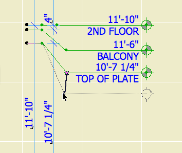
Levels. Use the object 'Elev Marker JAM8'. Elevation views should show the Z-height of each story. It is helpful to draw a dotted (not dashed) line through he elevation at each floor level. Dotted lines need to be heavy in order to be visible; use a 4- or 5-weight. In sections, levels should be should be shown for ceilings as well as floors, and for interior floor level changes (such as garage slabs). Level objects will auto-display their Y position, which is the height. They should be dimensioned to show the relationships among them.

Knee wall heights should be dimensioned in section.

In sections, unusual ceiling or floor conditions may be labeled with Slab Elev JM9. Examples: Lowered ceilings in small rooms, a stepped slab in a theater.

Roof pitches should be noted in section and elevation with the label Roof Slope JAM9.

Doors and windows should be labeled with Door-Window Label JAM9.

Structural members in section should be labeled with Description JAM9. Joists are shown 2D-only using 'Joists Sect 2D JAM9'. Our standards don't support modeling the joists.

2005-06-17.jpg

I'm still not totally comfortable with the SK routine. For example, if you place the SK title block in the plan, you run into trouble when the SKs overlap. And it's a pain to set the scale when using the title block within PM.

Here's what I'm doing as of now. It probably still can be improved, and as Vassos starts needing revisions I'll probably make further progress. This shouldn't be interpreted as standard right now.

Create a new layout in the SK folder. Use the SK Master, the one without the title block. Name the layout what you what to print on the SK. The autotext in the title block object will render the layout name.

Set up the title block in the AC detail window with the date, sheet ref and scale. Import the 'xSK Title' view into the layout. (Not the Master Layout.) Tip: In the Navigator, copy the title block drawing from the 'SK Blank + Title' Master. (Drag while holding Option.) Make sure you update it.

Select the title block drawing and explode it. That turns it into 2D elements. When you change the title block in AC later, this layout won't care.

Import the relevant view(s) to the SK layout. Tip: Copy the views from wherever in the set they live, and update.

Interlude: Drag-copying in the Navigator. You can easily move drawings between layouts by dragging them in the Navigator. If you hold down Option while doing so, you will make a copy. You can be sure you are copying rather than moving when you see the green plus-sign circle.

Once the drawings are in place, go to drawing usage, select them, and click 'Break Link'. This basically turns them into PMKs that are embedded in the layout book. In drawing usage their status will read 'Embedded'. When the views from which the drawings came are updated, these PMKs will be untouched.

The combination of exploding the title block and breaking the views' links means that the SK layout will stay as it is, whatever else changes in the project and layout book.

The SK thing is a tricky area, since AC and PM are not naturally inclined towards revision control in their current state.

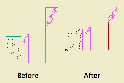
With the detail tool and a well-developed model, trim details can be developed pretty quickly. The oddball is rakes, since there's no way to cut a non-plumb section. You need to take extra steps to correct the distortion arising from cutting through sloped elements. A conventional resize won't work, because you can't restrict it to one axis.

The trick is to create a patch and then adjust its vertical dimension.


The goal.

1. Marquee the area you want in the detail and create a patch.

2. Figure out the conversion factor. There's at least two ways to do this, I like the first one.

a. SIN(90-RoofSlope). Example: 10/12 pitch is 39.8056º. SIN(50.194)=0.7683.

b. (True thickness of roof) divided by (plumb cut height of roof). These values are readily available in the info box. Example: A 10" roof at 10/12 pitch has a plumb height of 13.017". 10.0/13.017=0.7683. Tip: Much easier if your working units are decimal.

Four decimal places is fine. If the factor is greater than one you've made a mistake.

3. Now you can either a) drop one line into the patch's 2D script, or b) calculate the adjusted height of the patch and change it in the settings.

3a. Open the patch object. At the top of the 2D Script type:

MUL2 1, [ConversionFactorFromAbove]

For the 10/12 pitch, that's:

MUL2 1, 0.7683

Save the object.

3b. Multiply the 'natural' height of the patch by the conversion factor. Select the patch, and put the converted height in the Y field.

Either way, you're squeezing the patch so the vertical dimensions of the elements are right again. Horizontal is unchanged.

4. Create a detail. I recommend an independent detail, since the source view data for a detail generated from the window will never be right; it will be pre-patch distorted, and you'll have to delete all of it.

5. Place the patch object in the detail window. Tip: Cut and paste it from the section window. You don't want it hanging around the section anyway.

6. Select the patch and explode it (Cmd+=). Now you have 2D lines and fills as if you had generated the detail directly. Except: All the elements are of one big group. Also, there's an 'Air Space' fill element in the shape of the patch, which you don't need.

You can trash the patch from the library if you wish. It is no longer needed. On the other hand, it doesn't take up much space. Whichever.

UPDATE: Better info here.

Suddenly, Richard's AC could not open a file on the network, and would hang (rainbow ball of death) when attempting to browse a network resource, such as the Hotel. We noticed it when attempting to open another project in Attribute Manager; since the previous state of that Open dialog was viewing the Onion, hang.

All conventional treatments exhausted, I had to call tech support. They directed me to this knowledge base article, which has to with switching off a cross-platform browsing preference that we don't need anyway.

If you ever see this behavior in AC, here's the fix.

Make sure AC is not running. Open Terminal (Applications : Utilities : Terminal). Paste this text into the window and strike enter:

defaults write com.graphisoft.AC\ 9.0.0\ USA\ v1 InputOutput -dict "DisableCrossPlatformMountingFeatures" "<true/>"

That's it. Quit Terminal and relaunch AC.

If you drag a dimension string, the texts will re-center themselves on their segments, assuming the texts have not been moved manually.

You don't actually have to drag the string anywhere, just a drag and a double-click will do it.

The only way a dim text would be off center without you moving it is if you customized the text.

Who cares? You, because you probably changed some texts to read EQ or something, and re-centering them by hand is a cumulative chore.

So, after changing the texts to read whatever, (deselect the texts,) select the string, Cmd+D, clickclick. Note: if the dimension tool is active (very likely), you have to do a Drag command; cursor-drag will edit the witness line length. You can drag with the arrow tool and it works; I think the Cmd+D method is better since you don't have to be precise. Any texts that you moved manually will stay put. AC remembers which those are.

I just dimensioned all the Vassos ceiling lights on the electrical plan, which, if you've never had the pleasure, boils down to a LOT of EQ EQ EQ EQ EQ. So I was really happy with this discovery.

Sort of cross-posted here.

(Originally posted here. Added examples.)

Here is the Geometry Methods info box tile.


Geometry Methods are the ways of making a shape with a tool. The 'GMs' are only available in the info box, not in the settings. You can switch geometry methods in any tool by typing G.

The first button is one click placement. The object will be created with the default X, Y, and rotation. Example: A recessed light fixture, since it's not stretchy and it doesn't matter how it's rotated.

Second is rotated placement. Two clicks. First is anchor point, second is angle. X & Y will be the defaults. Examples: Anything that you would turn to face a certain direction. A lot of things. Sinks. Light switches. Sconces. Centerline symbols.

Third is rectangle placement. Two clicks. First is anchor point. Second is the diagonally opposite point. The same method is available for polygons (slabs, fills, etc.) Not all objects will be placable this way; only stretchy* ones. By this method you can graphically set X & Y, but you can't give values. Example: Crown Tool in coffer mode.

*Interlude: Stretchiness. Objects are stretchy if they have hotspots in their 2D scripts at the 0, A, & B extents, OR "Hotspots on bounding box" is on in their "Details". Don't worry about this now. An example of a stretchy object is Bed 01 in the Furniture folder. The only way to know if an object is stretchy is to try it, or look in the script. Most rectangular objects should be stretchy.

For "stretchy" placement to work, you have to have a corner set as the insertion node in the settings. If a non-stretchy node (e.g., the center) is the insertion node, you get one-click simple placement. In the plan preview window in the object settings, the insertion node has a box around it. You can choose a different insertion node there by clicking on it.

Tip: When you Option-click (pick up settings) on an object, the node you clicked becomes the insertion node.

The fourth button is rotated rectangle. Three clicks. First is the anchor point. Second is angle AND length of first side (X). Third is length of second side (Y). Example: Crown tool coffer in a rotated space. The same method is available for polygons. If a non-stretchy node (e.g., the center) is the insertion node, you get two-click rotated placement.

The key is not to get hung up on "rotated". I use this method all the time for non-rotated polygons, because you can use R to set the length of both sides on the fly. Example: counter slabs. When placing an object such as a bathtub this way, you need to know which way the object goes; X is first, Y is second. If you do it backwards you get the drain on the long side.

If an object is "linear", only stretchable in one direction, stretchy placement still works. If using rotated placement (4th), the second click only sets the angle, and the third click sets the length. Using the fourth button with a linear object enables you to draw it very much like you would a line. Examples: Lots. Drawing title, crown tool in straight mode, steel and wood beams, cut lines. Sometimes it's hard to predict which side of the "line" an object will be drawn; if it's wrong just mirror it.

Choosing the right geometry method saves a lot of after-rotating and -stretching, and is therefore much faster.

You can magic-wand a zone stamp to place a polygon using the geometry of the zone itself. It works even if the zone polygon is hidden, and saves you the trouble of finding an edge, since zone edges tend to coincide with lots of other stuff. Magic-wanding the middle of a room is often impractical due to interference of other lines.

Handy for finish-floor slabs, lower-the-ceiling-in-one-room slabs, floor material fills, etc. Just make sure your zones are updated first.

Cross-posted here.