I added all the plinth shapes I could find to the interior door casings. Not all plinths will fit all jamb casings; you need to know what you're doing.
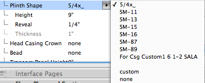
I added all the plinth shapes I could find to the interior door casings. Not all plinths will fit all jamb casings; you need to know what you're doing.

If you have a DWG or DXF from the surveyor, drop it in the floor plan and trace it. (Such a drop creates a drawing element in the plan.) If you trace carefully, the shape will be as accurate as the DWG itself.
But, very often, instead of a DWG from a surveyor you have a plat or 'location survey' from the homeowners' closing documentation. Even if you scan it in, you can't accurately trace it because it doesn't have any real lines. Scan or no-scan, you need to manually create the boundary polygon using the metes and bounds on the plat as a guide.
1. Set the working units. Set the length unit to decimal feet and the angle unit to surveyors' unit [sic].
2. Line tool. Pick a line on the plat, any line. Start drawing. Type A, which highlights the 'a' field in the coordinate box. Enter the angle of the line, which is something like N 26º 14' 51" W. Omit the punctuation; it's just n 26 14 51 w. When you finish typing, don't strike enter. Hit Option+A, which looks the angle you just put in the A field. Type R, which highlights the R field. Enter the length of the line, the hit return to finish it.
Don't worry if the line looks funny. The surveyors' units follow the project north setting, so if you haven't set north yet the direction will seem rather random.
3. Draw the next line the same way, starting at the end of the first line. Pay attention to whether the line goes in the expected direction. If it doesn't, move it so its other end touches the first line.
Why? In surveyors' units, any vector can have two directions, depending on which way the guys went around the lot. Following their numbers will sometimes give you a line that looks crazy, but it's just 180º off.
Do all the lines this way and hook them up.
4. In the case of an arc, do it last. They usually give you the degrees and the radius. Using the circle geometry method of the arc tool, start drawing by clicking anywhere. Move straight to the right and type R followed by the arc radius. Hit return. Type A followed by the angle, then return. Drag and rotate this arc to fit the other segments. If you have multiple arcs ask for help.
5. When all the segments are connected, magic-wand a fill element onto the whole thing and trash the lines and arcs. A fill is good because it can report its area, which you will need for the project information. Line type: Property Dot-Dash. Layer: +C Site Line.E Pen: 45 or other 5-weight.
When the boundary is done, drag and rotate it to the proper place with respect to the project. Use the boundary to create the grade mesh.
Once you have the north direction set correctly, you can use the Survey Dim RND9 object to dimension the boundary for the site plan.
Don't forget to put your working units back.
Now we have some standard details, in the form of module files, which you can drop into whatever projects might appreciate them. They are located at 3 Resources / AC / External References / Standard Details. These are distinct from the Assembly Type details, which specify the components of walls, roofs, slabs, etc.
I will define a standard detail as a building condition always done in a certain way, independent of superficial architectural characteristics. For example, a brick window header will always be flashed with the same technique, regardless of the size or color of brick, the joint finish, or the shape of the brickmould. Those architectural specifications would be noted in other details and/or in the specs. Further, standard details represent CYA-type technical matters that we want to be sure not to forget, so the easier to drop them in the better.
The first wave of these details concerns the heads, jambs, and sills of openings (doors and windows) in walls finished with wood siding, stone, and brick.
Create an independent detail window. Give it a descriptive name such as 'Typ Brick Window Head'. I like to use the ID field to keep the standard details separate from the 'real' details, so I would use an ID like 'Standard01'.
You can either merge or hotlink the desired module into this new detail window. Merge is essentially a paste operation, and the drawing elements will simply appear in the window and act normally.
Hotlinking maintains a live connection to the module file. If the module ever changes, you would get a notice to update it upon opening the file. Elements of hotlinked modules cannot be edited; the whole thing will act like a big locked group. (Module elements' nodes are square donuts instead of round.)
Which way is right. I will say merge in this case. As a 'Standard' detail, it shouldn't change often, and having fewer external references simplifies taking the project off-network.
Create a view of the detail window and drop it on a detail layout. Rinse and repeat.
Don't be distracted by the Standard Details.PLN file in that External References folder. The project file is the administrative resource for generating the module files. Here is a summary of my detail method as it relates to the assembly types. Here is the really sick module generation method, which has nothing to do with the end user. 'Sick' can mean 'gross' or 'cool'.
Please let me know immediately if you encounter a module with multiple stories. How will you know? Such a module will not merge into a detail (or any non-plan) window, and you will get a warning to that effect. If you try the sensible workaround of merging the module into the plan window and then moving it, you will eventually notice multiple empty stories added to your project.
Both of these outcomes are sick in the uncool way.
This problem started in AC11, when it became possible to save multi-story modules. (Previously, if you wanted a three-story module, you needed three one-story modules.) This feature has a crippling bug that was reported in early beta, yet remains unfixed. When you publish a module from a multi-story project, you have a choice of what stories to publish: All, Current, or a range. It doesn't work. When you attempt to publish a single-story module, you get a module with all the stories of the parent project, with the content of only one story, the one that was 'current'.
So, after cool-sick publishing the modules, I have to gross-sick open each one of them and delete the extra stories. Of course, some day I will tune up a detail and re-publish it and then forget to fix it, and you will be sad when you try to merge it, and then you will tell me.
I would like to take this opportunity to express my great displeasure with Graphisoft's current quality assurance standards. This is a major bug in a medium-size new feature. They have known about it for months. They have released four patches to the shipping version on top of a number of beta versions. This bug impairs the ability of serious firms to use Archicad at a high level. It wastes your time and mine. It adds to the apprehension about future releases and how long they, in turn, will take to stop messing up our workflows, if ever. Archicad 10 still has what I consider show-stopping bugs, but it will never be patched again.
It is infuriating today and worrisome for the future.
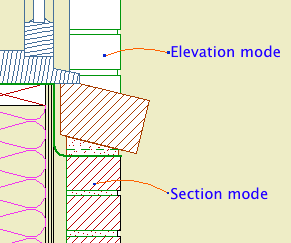
2D symbol for brick walls in large scale sections and details. It will alternate bricks and joints. The height of a brick is controlled by the Brick Triplet Height, which is the height of three bricks. You can directly set the Joint Width and Reveal.
In Section Mode, the width is set by the Brick Width parameter. In Elevation Mode, the width is set by the length parameter of the object. (I'm sorry if this seems a bit weird. The thinking is that in section you will always show a whole brick width, while in elevation you will often shorten the width to fit a window casing, e.g.)
The Mask switch fills the joints with a white fill in Section mode, so the object can cover a vertical wall line beyond. If the distant line is heavy, use the Nudge parameter to make sure the fill covers it. In elevation mode, Mask makes the entire object opaque, including the joints.
The Brick Fill and Mortar Fill should be obvious. The pens are set by the symbol, cut, and cut fill pens of the object's settings.
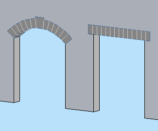
Make it Flat or not. If it's arched, you can set either the Spring Height or the Arch Height, and the other dimension will change to maintain the overall height.
If Flat is on, the arch/lintel can be Segmented (separate arch stones) or Solid (a one-piece lintel). With Flat off, the curved arch must be segmented and the Style parameter is hidden.
A Flat arch/lintel has options for the Bearing dimension and Angle at both ends. Example of angle usgae: A brick jack arch.
A segmented arch, Flat or not, will be made of stones measuring, at most, the Stone Max Width. You can have a Keystone, which can have its own Width. To omit the keystone, set the Keystone Height to 0.
The big new feature in this version is the Squiggly Stone option. This will give a (little) more natural shape to the lintel or arch stones. The squiggly parameters and behavior are different depending on whether the arch/lintel is 'Segmented' or 'Solid'.
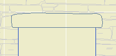
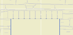
In the current version, a segmented arch will only be drawn squiggly at scales less than 1/4" (1/2" scale and larger). This is to conserve resources in 3D/section/elevation, because the squiggly arch uses a lot more polygons. If you want to override the scale control, turn on the Force Nicer Arch parameter. I'm thinking about a way to do low-scale squiggly joint lines, but it's not ready at this time.
Note: A solid squiggly lintel is always squiggly, regardless of scale.
The Joint Pen is used to draw the joint lines on a non-squiggly or low-scale arch. This pen should be 150, the usual surface hatch pen. In addition, squiggly arch stones are modeled using this pen, so they don't stand out so much.
Materials: The visible arch/lintel will use the Arch Material. For a Squiggly, Segmented arch, the visible, squiggly stones are actually thin plates applied to the front of the wall. (You can't tell.) Behind that, within the wall, is a regular lintel, built with none of its edges visible. This is so the arch appears consistently in section. This invisible piece takes the material of the edge of the wall. If you look at the shaded view and see a funny color within the arch, check the wall's edge material. (For stone walls, the edge material should be stone so the masonry reveals look right.)
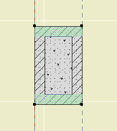
The overhead lines (Cased Op Lines) can be switched off individually.
Here are some 'recipes' for typical applications:
Precast lintel: Flat on, Solid, Squiggly off, lintel bearing>0.
Stone lintel: Flat on, Solid, Squiggly on, lintel bearing>0.
Flat Stone arch: Flat on, Segmented, Squiggly on.
Stone arch: Flat off, Segmented, Squiggly on.
Brick jack arch: Flat on, Segmented, Squiggly off, lintel angle>0.