On Land

Environment Information
At Rill Architects we run ArchiCAD on macOS. If you work at Rill, this is your stuff. If you don't, but you work in ArchiCAD, you may find something interesting. Anybody else, I don't know.
RSS
December 2007 Archive

All Entries | 1 | 2

Executive summary: A new layer for elements in layouts and in the title block worksheets. There should be no elements on the Archicad layer.

AC Layer
The Archicad layer is Archicad's own layer. It can't be deleted, hidden, or locked. Some layer then! Rare is the project element that should always show. These limitations make the Archicad layer approximately useless, and it is widely recommended that it not be used. That said, we have used it for a long time for a handful of always-showing cases:

• The title block object and other stuff in its detail/worksheet window
• Drawing elements on layouts starting in AC10
• Master layout drawings and annotation elements

And it's never given us any trouble, but.

The concrete reason to forswear use of the Archicad layer is that it interferes with Teamwork. The only way to have the Archicad layer in your workspace is to have 'exclusive access' to the project, which is inconvenient in a real shared workflow. It's true that we don't use Teamwork much, but you never know.

Rather than confront the question under deadline pressure some time in the future, I'm changing the standards and templates now to include a layer for 'Layout' elements. This layer, +Z Layout, holds any element placed directly on a layout, including drawing elements, texts, PDFs, etc. It is also the layer for the title block object and anything else within the title block worksheets. The layer is visible and unlocked in all layer combinations except 0 Working Model.

Once all that always-showing stuff is placed on a regular layer that could potentially be hidden, you might wonder how to make sure it always shows anyway. The layout environment actually has its own layer settings, which are maintained simultaneously with the model window layers. Changing the layer settings of one does not affect the other, thank goodness. The templates are set up with the +Z Layout visible in the layouts. As long as you leave it alone, it will always show. If you do hide it, probably by accident, and WOW you'll know right away when everything vanishes, turn it back on. Layout layers are unaffected by view changes. This should be a set-it-forget-it situation.

Some people use multiple layers to turn layout elements on and off, but I don't see the advantage of that for us at the moment. One concern would be that layout layers can't be saved, with views or otherwise, so the user must remember to manage the layers before publication. I would be inclined to handle such visibility control in the title block worksheets. Here is some AC-Talk discussion.

The other advantage of using this standard is that the Archicad layer rule is much simpler: Don't use it, full stop.

Template changes:
• New layer +Z Layout. Show in all combos except Working Model.
• All title block worksheet elements to the new layer. Use F&S for all elements on AC layer, then Edit Selection Set to change.
• Set layer environment layers to combo xxAll, which shows everything.
• All master layout elements to the new layer. On each master, use F&S and ESS as above.
• All drawing elements on regular layout to the new layer. In Drawing Manager, sort by Placed To, highlight all non-master drawings, change layer in settings.
• Change default layer of Drawing tool.
• Redefine Drawing tool favorites with the new layer.
• Save favorites.

# Milk Man...

This is the webcam of the school under construction with the money partly raised from the sale of the DVD of the performance of the kids' ballet based on the record by Deerhoof.

-James 2007-12-20-0505

A reference marker is a special object that can intelligently refer to viewpoints within the project or drawings placed on layouts. They also create viewpoints, which is a strange kind of double duty. Then you can also create viewpoints without markers... it's not intuitive overall. For most cases, you can think of a viewpoint as an application window. Sections, elevations, interior elevations, details, and worksheets are all viewpoints. So are schedules and even stories, but they are not related to the marker discussion in the same way. Everything in here applies equally to sections, elevations, and details.

A source marker creates a viewpoint. It is the viewpoint, in a manner of speaking. If you delete a source marker, you delete the viewpoint. If you copy a source marker, a new, additional viewpoint is created.

A linked marker is more like an object, though still a special one. When you place a linked marker, no viewpoint is created; the marker points to something. Any number of linked markers can point to a particular viewpoint or drawing. They are just pointers, and they can be created or destroyed without affecting anything else.

Both source and linked markers can refer to drawings.

You can have a viewpoint with no marker. Such a viewpoint is independent. You will very often have independent details. At this time all of our worksheets are independent. You can even have independent sections and elevations, but I don't see any advantage to these. Interior elevations can't be independent.

Choosing Source or Linked

When you get ready to place a marker, whether to draw a new section or refer to an existing detail, you will see these choices in the info box:

Marker creation options

When you select a marker, the options look like this:

Marker selection options

You can turn a source marker into a linked marker and vice versa, but don't. It's complicated, potentially destructive, and I'm pretty sure it's silly. Treat your viewpoints as 'real' things, and use linked markers to point to drawings in any way you like.

With Marker reference to
Marker ref to viewpoint
In our usage, markers usually refer to drawings in layouts, though they can also refer to viewpoints. Before a drawing is placed, source markers should refer to their viewpoints. In our section, elevation, and detail markers, you can tell the marker is referring to the viewpoint because the ID and name of the viewpoint are shown in the tag. The text is written with pen 10 (red), so if you print them they will appear empty.

In practice, a linked marker should always refer to a drawing. It makes for a smoother workflow if you place the drawing in the layout before placing linked markers.

When you choose to refer to the drawing rather than the viewpoint, you have three choices.

Marker reference to

The selected drawing lets you choose the drawing manually from the layout tree.

The first placed drawing of the viewpoint means you don't have to choose the drawing. The marker will find the first drawing of that viewpoint in the set and refer to that. You can choose this option before the drawing is placed. If you go this route, make sure the first drawing is the only drawing, or you are sure the first one is the one you want. N.B.: In our layout tree, the schematics sub-book comes before the CDs, so this 'first' thing will always use a schematic elevation instead of the same elevation in the CDs.

• Similarly, the first drawing of the selected view lets you name a view in advance of placing any drawing. When the drawing is placed in due time, the marker will refer to it. This 'first' method is safer, because 'view' is more specific than 'viewpoint'. For example, the schematics and CDs use different views.

With a source marker, you can only choose a viewpoint, view, or drawing associated with the marker's viewpoint. A linked marker can point to anything.

No drawing placed
If a marker is set to refer to a drawing but no drawing is placed yet, the tag will read #DrgID / #LayID. If you see this in a marker, it means the drawing isn't placed. Remember, if you see red text, the marker is still referring to the viewpoint.

Warnings about deleting markers

When you have a source marker selected and you strike delete, you will get a warning to the effect that deleting a source marker will also delete that marker's viewpoint, unless you choose to keep it as independent. If you confirm that you want to delete the viewpoint along with the marker, you be warned again, to the effect that deleting sections (e.g.) is not undoable. This second warning is as old as the section tool itself, and you know what it means.

If you delete a viewpoint from the Project Map, you will only get the warning about undoability. When a viewpoint is deleted in this way, its source marker and any linked markers are automatically deleted.

When you delete a linked marker, you don't get a warning, because nothing important or non-undoable is happening.

Somewhere, a roof is unhappy. Most likely, the angles of nearby roof edges are causing the geometry to turn inside out. The report will say something like:

Invalid polygon, self intersection or hole intersects boundary. (Roof 004)

This is actually helpful! Use find and select to find a roof with that ID, and you can fix it. The trouble is that you probably have a lot of roofs with identical IDs, and you can't tell which of the n roofs is the problem.

If the IDs were unique, the report would lead directly to the bad guy. So you need to change the IDs of all the Roof 004 elements. You certainly can do this one at a time, and it will work.

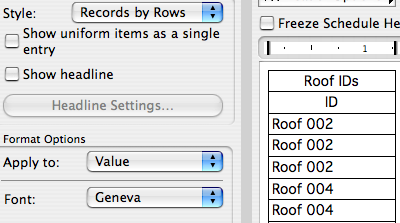
Instead, use an Element Schedule to isolate the roofs, and correct the IDs.

Make a new schedule (Document -> Schedules and Lists -> Schedules -> Scheme Settings; Create New). The criteria:

Roof ID criteria

For the fields, you just need 'ID', from the General heading:

Roof ID fields

This will give a schedule with all the roofs whose ID is not blank:

Roof ID preview

Make sure the 'Uniform Items' checkbox is off. If it's on, you'll get one line item for Roof 004, regardless of how many there are, defeating the purpose.

Now all you have to do is change all (but one) of the Roof 004 items to something unique. You can use numbers in the same pattern, as long as they aren't used elsewhere in the schedule, or you can add a, b, c, or something to the IDs.

Next time you run the 3D, section, or elevation window, you'll get the report again, but this time you can use the ID to find the specific element.

AC11 has a model view option to put the floor plan into reflected ceiling mode. It only works for objects, not regular elements (wish wish wish). I have several objects that take advantage of it.

This is the basic code you need to have a symbol draw itself differently in floor plan and RCP mode. The idea is that depending on the state of the switch, you set certain attributes, draw some things and not others, etc. Often, the shapes are the same, but the line switches from dashed to solid; stuff like that.

!! Parameters
!! plnPen : Plan Pen (0=Match)
!! plnLT : Plan Linetype (0=Match)
!! rcpPen : RCP Pen (0=Match)
!! rcpLT : RCP Linetype (0=Match)

!! If attributes are 0, set them to object settings
IF rcpPen=0 THEN rcpPen=L_
IF rcpLT=0 THEN rcpLT=SYMB_LINETYPE
IF plnPen=0 THEN plnPen=L_
IF plnLT=0 THEN plnLT=SYMB_LINETYPE

!! Request state of ceiling switch
rr=REQUEST("floor_plan_option","", storyViewpointType)
!storyViewpointType=1 !! testing

IF storyViewpointType=1 THEN !! ceiling
	!!Set ceiling attributes
	PEN rcpPen
	LINE_TYPE rcpLT
	!! Draw ceiling-only parts
ELSE !! floor plan
	!!Set floor plan attributes
	PEN plnPen
	LINE_TYPE plnLT
	!! Draw floor-plan-only parts
ENDIF

!! Draw parts common to both plans, using whichever attributes
LINE2 ...
RECT2 ...
POLY2 ...
MVOlist
Model View Options, formerly known as Display Options, can be organized into combinations, kind of like layers, and MVO combinations can be saved with views. Naturally, this is all set up in the templates. MVOs are completely separate from On-screen View Options, which are screen-only and do not affect output.

The MVO dialog has three divisions. Options for Construction Elements concerns the display of real things, including openings, columns, beams, and markers. Options for Fills and Zones concerns how different categories of fills are displayed; turning cover fills on and off, e.g. Options for GDL Objects has only one item at the moment, the beloved Story Viewpoint Type, also known as the ceiling switch.

The keyboard shortcut to open the dialog is Cmd+9. I think the MVO dialog is pretty good about previewing the effects of most of the controls.

Rather than describe each combination, or heaven forbid build a table, I'll describe the A1/A2/A3 combination, then how the others differ.

More»

Shape Tag

I tweaked the Shape Tag object so you could have a masking fill within the polygon.

The intent is to show a solid white fill. To ensure wide compatibility, I've provided parameters for the fill and the white pen. Non-locals may want/need to change the defaults to their preferred solid fill and white pen.

Download

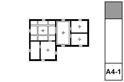
Sheet A4-1

The reflected ceiling plan is a universal drawing type that Archicad simply does not handle very well. We took a medium-size step forward in Archicad 11 with addition of the 'Ceiling Plan' model view option for GDL objects. This allows object developers to make objects that draw themselves differently whether the 'Ceiling Plan' or 'Floor Plan' setting is active. But this switch only applies to objects, and beams, slabs, etc. don't know you want a different linetype when they're overhead as opposed to on the floor. Hopefully, this switch will soon apply to all elements, and we will have dedicated attributes for 'Ceiling Line Type', 'Ceiling Pen', and 'Ceiling Cover Fill'. I have wanted this for a while.

In the meantime, the RCP still demands a lot of tracing of modeled elements. It's better than it used to be, but it's still one of the least unified drawings.

What shows:
• Walls
• Ceiling trim and finishes
• Ceiling fixtures including lights, fans, and mechanical fixtures
• Floor elements, including deck edges, stairs, counters; traced with a dashed line

More»

Location: 06 Wood & Plastic

A beam, or any other ceiling element, should be shown dashed in the architectural plan, because it's overhead. That same beam needs to be shown solid in the reflected ceiling plan, because then you're upside down looking straight at it. Using a conventional beam element, you would draw it with a dashed line in plan. But you can't show the same element in the RCP, because you can't make the beam draw itself solid. So you trace the beams with lines.

In Archicad 11, we have a model view option which allows objects, but only objects, to be drawn differently in floor plans and ceiling plans. This object is a simple wood beam that responds to this switch, so you don't have to trace it in RCP. There are limitations to using this instead of a beam element, see below. But for a simple beam such as a timber, you definitely should consider this object.

Size: Choose a dimensional lumber size, or choose 'Custom' and set the Depth and Thickness manually.

Slope: The usual roof slopes, or a custom angle. If the beam is sloped, parameters are available to control the Top and Bottom edge angles.

Roll Angle: Turns the beam around the long axis. If the beam is sloped this parameter is not used.

Plan Cover Fill: Just what it says. Turn it on and set the attributes, or don't.

RCP Attributes: The Pen and Linetype that will be used when the ceiling switch is on. When the switch is off, the object's 2D symbol will be drawn with the object's settings. In practice, the object should be set to use a dashed line, while the RCP linetype is solid. The pen doesn't really need to be different in most cases, but the option is there.

Pay no attention to where it says 'Transparent' when the pen is zero, and 'MISSING' when the linetype is zero. Those indicators are automatic and I can't get rid of them. In our case, zero means 'Match the object's settings'.

RCP Cover Fill: Just what it says; this fill will be used when the ceiling switch is on. This can give you some ability to show beams stacking in the ceiling, such as joists running over a timber beam.

Plan Lines: The symbol is a rectangle, with Start, End, Right, and Left lines. Any of these can be turned off, to make the beam meet a wall more cleanly in plan, for example. If the Roll Angle is non-zero, you will also have the option of showing the Roll Corner Line in RCP. This line won't show in the floor plan.

3D Pen: If this pen is non-zero, it will be used in 3D instead of the object's plan pen.

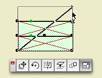
Start and End Miters: Turn these on and you can miter either end of the beam to meet other elements. The angles are graphically editable like any other mitered thing.

We have a special layer for elements we wish to see in plan and RCP, A Ceiling All. Use that layer for this beam.

Limitations

This object is better than a beam element if you're just talking about the RCP. But there are plenty of ways it's not as good. One big disappointment is that you can't cross a pair of them and have them clean up in 2D and 3D. Another, beams can use custom profiles. A weird profile object has to be coded.

So, this object isn't a replacement for all ceiling beams. If it's a cased beam, you'll want to use beam element with a custom profile. If the beams cross, you need beam elements to make them clean up.

And if you're using real beams, you need to trace in the RCP. But, tip: If you have crown inside coffers, you might be able to skip out on the tracing and just let the crown objects (on the F Trim Crown layer) imply the beam shapes.

Another potential frustration is the case of a structural, visible timber beam. Normal structure beams are created with the Wood Beam object, which gracefully labels itself in the framing plans. The layer for these new ceiling beams can't do this, because I don't have a practical way to show the beam in all three plans, but the text in only the framing plan. A promising solution would be to create a label to refer to the beam, which could then show only in structure. Alas, here Archicad has stymied us again, because you can't show a label when the labeled element is hidden. And we can't show the beam itself because it's dashed. And I'm not putting the structure plans in ceiling mode, because I have no idea what the side effects of that would be.

For this case, model the beam using the RCP Beam object, and place another (Wood Beam) object on the +S Struct Note layer, with the Model parameter off.

With Drawing Title 10a you can:

• Set the Orientation of the title. You can have the title rotate to align with the Drawing (default), the Layout, or a Custom Angle. Use the Layout option to keep the title horizontal when you rotate a drawing. This is optional, and it's not always right. For example, if you rotate a wall section to fit on the sheet, the title should rotate too. I can't think of a purpose for Custom Angle, but it wasn't hard to put in there. If you do ever use it, the angle is graphically editable.

• Choose a manual scale from a list. Leave the field empty to use the drawing's true scale. This is usually correct. To show no scale text, choose 'blank' from the list. You need to set a manual scale for a scanned detail PDF; now you can choose it from a list.

Location: 06 Wood & Plastic / 2D Wood

A 2D symbol for plates, blocking, or other non-finish wood. This one replaces Lumber Continuous JAM81 and Lumber Blocking JAM8.

If you Use Standard Sizes, you can select the Board Size from the list. Better, you can stretch the symbol graphically, and it will snap to the standard sizes.

Width stretch
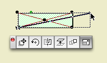
Stretch it by the corner to change the width.

Thickness stretch
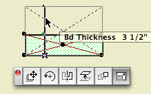
Use the extra node to change the thickness.

With Use Standard Sizes off, you can use any dimensions and stretch the symbol whichever way.

The Cross can be an X for continuous lumber or a slash for blocking.

Stack Units
Stack Units lets you stack multiple boards of the same dimension. Stretch the corner in the thickness direction to graphically create multiple boards.

There are separate pens for the Outline and the Cross.

Board Label
The optional Label places the nominal dimension along each side.

The Fill switch turns the symbol opaque white.

Location: 13 Special Construction

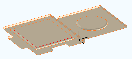
Two objects (primarily) for cutting coved recesses into ceilings, using solid element operations. One's a circle, one's a rectangle. Guess which is which. The parameters of each are similar.

The fillet radius must be less than or equal to the height. The resolution of the fillet is controlled by the Fillet Facets parameter. For the disc, the Resol parameter controls the resolution of the circle.

You can turn the objects upside-down with Flip Z. I can't imagine many cases for doing so, but you never know.

In practice, your ceiling slab will be the target, and the object will be the operator.


The 11 version of these objects adds the ceiling switch-awareness that we've used previously in Soffit Cutter JM11 and Ceiling Line JM11.

Sheet A3-2
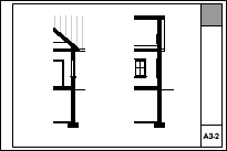
The big difference between a building section and a wall section, besides the scale itself, is that the wall section has much more fine detail.

The additional detail of a wall section comes from (some) scale-sensitive model elements, along with 2D geometry and annotation placed in/around the modeled section. That's right, drawing. But this kind of drawing doesn't leave the model behind, and the section window remains live. In section, your modeling goal is an accurate 'envelope' of empty poché that looks clean at 1/4" scale, and can accommodate fine detail and annotation at wall section scale.

More»

Site plan fragment
What Shows

Note, November 10, 2017: Anywhere you see the layer +C Site Annotation, you can use the layer +C Site Note if the current project doesn't have the annotation layer. (This layer is quite new as of this update.) The difference is not important unless the site is being shared among multiple projects. If the site is shared, the annotations layer is for permanent data about the site, such as north direction, survey dims, and topo labels. Notes specific to the project go on +C Site Note.

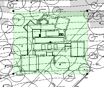
• General. The site plan is generated from the First Floor story. The 3D grade mesh is not shown because its pen and linetype options are too limited.

• Property boundary with metes and bounds. For the boundary, use an empty fill. (Only a fill can report its area, and you'll need the property area for the project information.) If north is set correctly and the boundary is precisely drawn, you can use and object for the metes and bounds, Survey Dim RND9, located in Graphic Symbols. Layers: C Site2 for the boundary, and +C Site Annotation for the text.

• North arrow object. North Arrow JAM9, located in Graphic Symbols. If north is set correctly, you can turn on the 'Use Project North' parameter. Layer: +C Site Annotation

• Setbacks. Layer: C Site2 Use lines, arcs, or polylines. Setbacks should be labeled 'BRL' (building restriction line). Special restrictions can be labeled more specifically; 'Conservation Easement', for example. Layers: C Site2 for the lines, and +C Site Annotation for the text.

• Topographic survey contours. If available. Use splines. Don't use lines, polylines or arcs. If you have lots of little segments, the dashed lines will never look right. Typically, we will get contours at two-foot intervals. The sea-level elevation of each contour should be called out, unless the contours are very closely spaced. In these cases, labeling only the ten-foot contours is OK. Layers: C Topo Existing and New for the splines, and +C Site Annotation for the text.

For boundary, setback, and topo text blocks, pay attention to the anchor point. This will help the blocks stay in position if you do multiple site plans at different scales.

• Building footprint. Layer: +C Footprint.N The footprint is the outline of the building as it meets grade. You will probably use the basement plan to get it. With the Site Plan layer combination active, show the A Wall Ext and S Wall2 layers. Trace the wall outlines with a polyline. You can show the basement story as trace (FKA ghost), or draw the polyline on the basement story and cut/paste it to the first floor.

Show dimensions from the footprint to the property boundary at key locations. For an addition project, the addition portion of the footprint should be filled with a diagonal pattern.

• Trees. If available. Use the object Tree JM10, located in 02 Site / Trees. Don't show removed trees unless you need to. Layers: L Tree2 or L Tree A. Trees on the 'A' layer will also show in the architectural plan. If you have modeled trees, you can place them on these layers or use L Tree3 to hide them in plans.

• Top view of building. This can be a roof plan or a 3D top view. This is a separate drawing overlaid on the site plan drawing.

• Additional building-related 2D elements. Anything you can't get to cooperate with the top view drawing can be drawn separately. Layer: +C House Line.

• Driveway. The layer L Drive2 shows in the site plan layer combinations. If you find that showing this driveway conflicts with the site plan somehow, you can modify the layer combination to hide it, and then redraw it with lines, arcs, and polylines on the C Site2 layer.

• Street. Layer: +C Site2 Use lines, arcs, or polylines.

• Notes. Label the major site and project elements. These are, at least, the existing house and addition, the driveway, pools, large terraces, septic fields. Layer: +C Site Note.

Line Types

• Boundary: Property Dot-dash
• Setbacks: BRL long dash
• 2' contour: Dense dashed
• 10' contour: Long Dashed
• Driveway and street: Solid
• Footprint: Dense Dashed

Fonts

The usual, but to review: Lucida Sans for notes. Tahoma for dimensions including boundary data. The street name looks nice with a serif font; use Times.

Top View Drawing
In the site plan, the top view of the house is a separate drawing.

Why? The site plan is generated from the first floor. The roofs are only seen in their entirety on the roof story. The only way to get the roofs on the first floor is to draw (trace, copy/paste, whatever) them. We don't like drawing things. Especially things that can draw themselves, especially things we have to keep checking in on to see if they are drawn properly. We want a top view drawing that maintains itself like any other model view.

There are two ways to do a top view so that it remains live: A plan view from the roof story (like the roof plan itself), or a hidden line top view generated in the 3D window. I think the 3D method is better. The 3D view can show elements of all stories, while the roof plan will use the story settings of individual elements. There's no issue of display order in 3D. A roof plan drawing would have the advantage of generating a little bit quicker, but that's not enough to change my mind.

The templates are set up with a view in the 3D views folder called 'Top View'. You might need to change the scale of this view; obviously it needs to match the scale of the main site plan. The other settings are:

• Layer combination: x Shoot Roof Plan Top View. (Update: I changed the name for clarity.)

• 3D Projection Settings: Top view, azimuth=270 (Camera at bottom).

• 3D Window Settings: Internal Engine, hidden line, vectorial hatching off, shadows off, transparency off.

The trickiest part about the two-drawing approach is aligning the top view with the main site plan. For some reason, we don't get the snap points (midpoints, e.g.) for lines within drawings, so we can't line up a roof edge midpoint with a footprint line midpoint. Fortunately, for most purposes, good enough is good enough. Zoom in and eyeball it. Make it look good. Remember, the dimensions will be to the footprint, which is drawn precisely in the main site plan drawing. If you do need a precisely placed top view, you'll need to place some temporary alignment elements on the first floor.

Make sure the top view's drawing element is set to have a transparent background. The pen set of thew drawing should be Layout 1/8", which turns the heavy lines a little less heavy.

Heads up concerning the issue date in the title block. I'm getting very erratic results when publishing; sometimes the title block drawing (on the master layout) updates automatically, sometimes it doesn't. If that drawing doesn't update, your title block data will be wrong, including the date.

I have confirmed that the drawings on the master layouts are set to auto update. That should be all it takes, but it's not.

For example, I changed the date and then published a PDF. The dates on the resulting PDF sheets are not changed. I immediately published again, without making any changes anywhere in the project. Now the title block is right.

Erratic.

The title block drawing will always update if you open its master layout. It seems it will also update if you open a regular layout. But I have seen cases where the layouts of some masters are updated but not others; it probably depends on what regular layouts have been opened.

But, each layout automatically opens as the publication happens! Yes, and it skips updating the master drawings. Sometimes.

Once again, we have an output-related, liability-hazardous, supposedly-automatic behavior where Archicad can't quite get the door all the way shut. And once again we have to follow it around making sure it's using its litter box.

My recommendation: If you are publishing anything where the date is critical (that's anything you're giving to anyone else), before publishing, open each master layout that is in use. Essentially, that's all the masters of a given size, just to be safe. Opening the master should trigger the auto update of the title block drawing, and then you should be set.

Date LOL

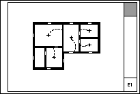
Sheet E1
What shows: Walls, stairs, counters, decks, appliances and mechanical equipment, and all electrical symbols.

More»

Isn't north up? Probably not. Since the orientation of the project is driven by the geometry of the plan, north can be any which way.

Project North
In the Sun dialog
The north direction for the project is set in the Sun dialog. You get there via the Sun button in the Camera settings box, or via the More Sun button in the 3D Window Settings dialog. MORE: Karl Ottenstein points out that you can also go directly to the Sun dialog by right-clicking on any 3D viewpoint (camera, axon, etc.) in the Project Map, or on any 3D view in the View Map.

Note: Though it's called 'Project' north, it's true north, in that it's the only north, and the north used by the sun settings. Archicad doesn't directly support a project north environment variable separate from true north.

There are at least four reasons to set project north correctly:

• Accurate sun shadows

• Automatic orientation of north arrow symbol objects.

• Automatic dimensioning of metes and bounds using the Survey Dim RND9 object.

• Correct naming of interior elevations with the Orientation autotext. (A real project north would be nice here.)

For the purposes of sun shadows and interior elevation names, you can eyeball the north direction by moving the pointer in the Sun dialog. A degree or two off isn't going to hurt.

For the metes and bounds to work, you need to set the direction exactly.

More»

All Entries | 1 | 2