Some typical applications for Wood Beam JAM9.
« Newer | All Entries | 1 | 2 | 3 | Older »
• Switch the title block to the RND9 version. Required. Use Cmd+Opt+click on the new object to retain settings. This is very important. If it fails, that is, you get the new object with default settings, cancel out of the settings box and try again. Delete all the hotspots. Place new hotspots in the sheet number box and the corners of the main drawing area.
• The grays as they come out of the new plotter are all darker. This affects the gray poche in the walls, etc. and the gray lines we use for floor and material fills.
The poche is a little dark, but we can live with it. If you change it it will look better, but it's a chore: You must change the fill background color of all 3D building elements (walls, roofs, slabs), and the background color of all the skins in composites whose settings are used in elements, and the fill color/background color of any masking fills, and the fill color/background color of any objects that show poche in plan or section, keeping in mind that some of them have special parameters for these fills. A chore. If you choose to go through with it, use pen 50. This is our new, dedicated poche pen. The idea is to make the next gray revision simpler; with a dedicated pen, we can just change the color of it rather than the settings of dozens of elements. I wish I'd thought of it sooner. So, poche pen change: Optional.
The fills, however, aren't quite OK. They should be changed to pen 150*. Strongly recommended. The fills include:
1. Fill elements, many of which will be on the F Floor Fin2 layer. Use find and select, on each story, for fills with pen 93.
2. Cover fills on 3D elements, including slabs, roofs, meshes. Do this in the 3D window to get all the stories at once.
3. Vectorial hatching pen on materials. You have to do each material separately in Options -> Attributes -> Materials. (Attribute Manager doesn't work for this.)
• In addition to the grays being darker, all the line weights are heavier, so we need to make all our pens slightly thinner. You will have to do this by hand in PlotMaker. In Archicad, you can use Attribute Manager to import the pens from 3 Resources : Attributes : Color Pens 0105. Required.
All the changes discussed above will be made in the templates.
*UPDATE: This used to say 92. 92 is the right color for plotted output, but in Archicad it looks too light on the screen. Read this post about the new material fill pen. As for changing the pen, either 92 or 150 will work in PM.
This is an unpleasant task you should never have to do, unless we get a new plotter. You don't even have to do it then.
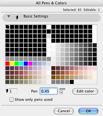
On the Options menu, All Pens And Colors. You get this:

A pen has two attributes, color and width.
Set the width using the field marked "Pen". Make sure the units are mm, not Pt (points).
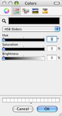
To change the color, double-click the pen's square in the grid, or select it and click "Edit Color". I recommend using the HSB sliders to edit color.

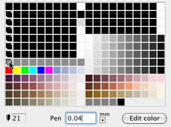
You can select multiple pens at once and edit their color or width together. Cmd+click on pens to accumulate them, or Shift+click to select a range. Like a lot of things.

Selecting all the pens between 21 and 141.
Editing pens in Archicad is similar, but we can use Attribute Manager instead.
The zTemplate folder has been updated to accommodate the new SK layout tools. If you need to issue SKs for current projects, you should bring the stuff in.
In AC:
1. Create an independent detail window with the ID 'xSK Block'. The name can be blank. Set the scale of the window to 1.
2. Place a 'Title Block SK RND81' object in the window. Place hotspots at the corners of the white space.
3. Save a view of the window in the #2 CDs viewset, Notes folder.
Note: This view is used in PM to generate SKs where the imported drawing does not have the SK title block in it, such as a scanned image.
4. To place SKs in plan or section windows, you need to create the layer '+Z SK Title'. (Everything in that article is true, except the misleading parts. This new layer should be hidden and unlocked in every LC, which is what happens naturally, except for the LC selected when the layer is created. After creating the layer, hide it in the current LC and click update.)
In PM:
1. In the Tree By Subsets view of the Navigator, right-click on the layout book name and pick 'Create New Subset'. Call the subset 'SK'.
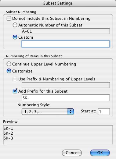
2. Right-click the SK folder and pick 'Subset Settings'. Make the box look like this:

Subset Settings, really just auto-numbering setup.
3. File | Import. Navigate to 3 Resources>SK>SK Layouts.lbk. In the Import dialog, check the box next to the layout book name, all the way at the top. This means you will import everything. Click 'Import'.
4. You should get two master layouts, 'SK' and 'SK Empty + Title', and one regular layout 'SK Sample'. Move the 'SK Sample' layout into the 'SK' folder. With the 'SK Sample' layout selected, check the settings at the bottom to make sure it's linked to the 'SK' master.
As you need new SK sheets, you will need to create new SK layouts and link them to the appropriate master. If the SK comes from Archicad with a title block, use the 'SK' master. If you are importing a drawing without a title block, use the 'SK Empty + Title' master. SKs of both types should be kept in the SK folder, in the order they are created, so they number themselves properly.
See also:
Sketch Revisions (SKs)
Title Block SK RND81
v2 is here. It seems to work.
Two gotchas so far (maybe you'll be lucky): 1) In PM, after stretching a frame with the arrow tool, frame nodes will not be detectable until you rebuild. Scroll-zooming forces a rebuild so that takes care of it. 2) After rebuilding drawings via drawing usage, the layout window becomes unresponsive. Minimize the window to the dock using the yellow title bar button. Bring it back, and it's OK. I think GS's beta testing consists entirely of demonstrating the software to their dogs. I digress.
The howto follows.
This is the old way. I decided to keep it for historical interest.
Building on the ability in OS X to save PDFs from the print dialog, we can easily create PDFs of drawing sheets. In PlotMaker 3, you can print multiple sheets at once to a single document, making one PDF of an entire set.
The necessary layer and view modifications for 1/2" scale plans in current projects. These changes have already been made in the templates.
Which you need to do from time to time, for several purposes.
Don't.
Remember our layer system is the result of lots of work on lots of simultaneous problems. As such, it is hard to improve but easy to break. Trust me. Further, layer management is far and away the most unpleasant standards task in the whole operation. You don't want to get involved.
OK, sometimes you have to. Maybe you really need a new layer. Maybe I told you you need one. If you're going to do it, you'd better do it right.
Select an existing LC that is similar to the one you need to make. Click 'New'. (The other one. Lower left.) Put in the new name. Make changes to the showing and hiding of layers on the right. Click 'Update' at the bottom. OK and save.
You will probably need to create views for the new LC.
See also:
Creating Layers
« Newer | All Entries | 1 | 2 | 3 | Older »
