

There are three main ways to create views in AC10, plus one more you should never use. The templates have most of the commonly needed views already set up, but it's not unusual to need more.

The model is in there. Don't look at it, just imagine it. Think of the real buildings you can't see at the moment. The Lincoln Memorial is there. Trust me.
The model is before everything in the Navigator. No model, nothing to Navigate, right?
The Navigator in AC10, besides being indispensable to your productivity, is good illustration of ArchiCAD's intended model-to-deliverables workflow.
Archicad 10 finally gives us the ability to place PDF files in layouts, as well as other project windows.
PDF-in-layout will become the standard method of placing non-Archicad info in drawing sets. Any file (Word doc, spreadsheet, etc.) can be saved as a PDF via OS X's Print PDF facility. In the current templates, the abbreviations and general notes are PDFs. It's the new stickyback.
Since you can place PDFs as model windows too, you may find it more convenient to use PDFs for topo surveys, plats, and the like.
PDFs become drawing elements. Since drawings are polygons, you can crop the PDF however you like with the pet palette.
There are several methods for placing PDFs, in rough order of convenience:
• Drag the PDF file from the Finder into the Archicad window.
• Use the Drawing tool. Click where you want the file to land.
In a layout window, you get the 'Place Drawing' dialog. Choose 'External Source' and then 'Browse'. Navigate to the file you want.
In a model window, you can only place an external drawing, so you immediately get the Open dialog, where you can choose the file.
• File -> External Content -> Place External Drawing. Select the drawing in the dialog box. (Least convenient method IMO.)
Whatever method you use, you can only place one page of a PDF at a time. If the PDF has multiple pages, you will get a dialog box where you can choose the correct page. To place multiple pages requires multiple drawing elements.
Since they're drawings, they can have titles, but they usually shouldn't, right? Make sure the title is set to 'None'.
Like all external drawings, PDFs will be Manual Update by default. If you modify or re-save the PDF, remember to update the drawing. I don't recommend setting external drawings to Auto Update.
If you take the project file off the network (home, e.g.), you will get a warning that the source file for the PDF can't be found. This is usually not a problem. The drawing will still appear, you just can't update it. When the project is reunited with the network, the warning will go away, and you can update the drawing as needed. (Note the similarity to Hotlinked Module behavior.)
I've taken another stab at standardizing the Work Environment. This for AC10 only.
The Active Layer palette is accessed on a submenu of the Layers submenu, which might be on Options (9) or Document (10) or somewhere else by now. You mean the Quick Layers palette? No. Active Layer.
This palette does exactly one thing, and I use it for exactly one purpose. It switches between the default state of 'Individually Set Layers' and the weird state of 'One Active Layer for al Element Types'. That is, it can set all the tools to the same layer in one go. And it can put them all back to the layers they had.
No, I wouldn't want all the tools on one layer, ever. I don't know why they made this thing, but here's what it's good for. Attribute Manager will report that a layer is in use if it is the current default of a tool. So you can't really tell if an element is on the layer or not.
So, use Active Layer to set all the tools to the Archicad layer. Set the palette to 'One Layer' and then set any tool to the Archicad layer.
(The other source of phony checkmarks in Attribute Manager is Favorites.)
When you close the Active Layer palette, or close a project where all the tools are 'One Layer', you'll get a dialog asking if you want to keep the One Layer, or Revert to the individual layers. You should choose Revert. (Of course, if you've deleted most of the layers, there's nothing to revert to, but it doesn't matter.)
It is not possible to delete the entire Favorite list at one time. You can only delete them one at a time, which, if you have a lot, no thanks.
But you can write over the entire Favorites list with another list. If this list happened to have, say, one item on it, well that would be pretty easy to delete.
We have the Favorites file 'Blank.prf' for this purpose. It resides at 3 Resources / AC / Favorites. It consists of a Favorite for the Hotspot tool, Archicad layer, pen 10, that's it.
On the flyout on the Favorites palette, choose 'Load Favorites', and open the Blank.prf file. You will get a dialog offering to merge or replace the current list. You want to replace. (Merge adds the new list to the old.)
Delete that hotspot fave and you've got your blank slate.
Why delete the Favorites? It helps clean out attributes. Attribute Manager will report that an attribute is in use if it is part of a Favorite. With no Favorites, it's one less place to look before you're sure you can delete something.
And of course you can clear them temporarily. Save the Favorites you are using, clear them, do whatever you need to do, then load your saved list back.
Every attribute (pen, fill, linetype, layer, etc) in AC has a unique ID number. Internally, AC handles attributes by their IDs. The names are just for us. The IDs control the interactions between attributes, and the default parameters of objects. When a composite or material has the wrong fill, or an object comes in with a surprising default setting, it's often because IDs have become tangled up.
They don't get tangled up on their own, but it seems like they do, as we create and delete attributes, merge them from other projects, etc. Attribute Manager gives us some ability to manipulate IDs, but it's tricky.
Here's an example of the gymnastics you need in order to work with the antiquated attribute ID system. On the other hand, at least it's feasible. On the final hand, it is unbelievable that we can't edit IDs directly, and really we shouldn't have to interact with them at all.
It's also a good example of how attribute IDs can mess things up, which is why you have to hack them.
In this case, all the openings in the Archicad library default to drawing their overhead lines with linetype ID 4. In the templates that ship with AC, that ID is a dashed line, which is fine. In our templates, ID 4 is the 'Layout' linetype, a dot and dashed thing. So unless you change it, the openings look like this:
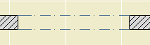
Errrrrrg.
Moral: Generally speaking, attribute IDs are strong and attribute names are weak. AC only cares about the '4', not the name 'Dashed', and not the dashes themselves.
The other moral: Especially where libraries are concerned, it's best not to fight default IDs if you can avoid it. It's better to fix one linetype rather than a whole pile of objects. That's where the gymnastics come in.
The Element Information palette is accessed at Window -> Palettes -> Element Information. It's a palette; it will hang around until you dismiss it, like Find & Select or the solid elements thing, whatever ridiculous name it has.
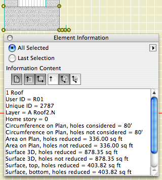
There are six sections of data, each activated by one of the buttons. Any or all of the buttons can be active at once. They are:
Properties: ID, layer, and story. This is the only place you can directly read the home story of an element. I don't know why this has to be such a secret.
Size: 2D dimensions. Lengths, widths, and/or 'circumference', which we would expect to be called 'perimeter'. Use fills and this info to do that new/existing comparison the permit people want sometimes.
Area on Plan: 2D Area. Self-explanatory, but note that it's different from the 3D surface area, which is coming up.
Height: Pretty obvious for most things. For roofs, it also gives the perimeter I mean circumference of the top surface. For walls, conventional roof trimming is not considered.
Surfaces: Areas of all the 3D surfaces. Note: Solid Element Ops are taken into account.
Volume: What it says. SEOs work here too. I have actually used this for a back-of-envelope cut/fill grading calculation.
This isn't really calculation, it's just inspection. To actually do anything with the data, besides write it down or copy and paste it, requires list schemes.
Here is the Graphisoft product page.
Here's a short feature list. It reflects my personal biases. Things they are really excited about, I might not even mention!
• PlotMaker is no longer with us. Layouts are part of the project. For large projects, it might be advisable to have the model and layouts in separate files, but they would both be PLNs.
• There is a cutting plane associated with each story, which can be used to automatically display roofs, and other elements, with their true relationship to the current story.
• You can create custom profiles for walls, beams, and columns. I'm not so excited about the beams and columns, since they have no parametrics, but the walls have a lot of potential.
• Interactive Schedules have finally reached version 2. They are greatly improved, and we will use them more and more. Most exciting: Automatic drawing lists.
• PDFs can be placed in layouts.
It is slated for release in the first week of May.
We will not rush into this one. As of this writing, I do not plan on migrating projects. That is, if you started in 9, you should finish in 9. And, I don't have templates for 10 yet. So you can't start new projects in 10 either.
10 is a worthwhile upgrade. But it will be quite different, especially in the documentation area. AC9, and our AC9 methods, are very reliable and not to be abandoned lightly.
ArchiCAD is designed to automatically save project data periodically. In the event of an AC or system crash, project data can usually be recovered. AutoSave is described on page 150 of the AC9 Reference Guide.
Yes, it's a little late for a New in 9 post, but that's what happens when I pretend I'm going to tell you, briefly, anything meaningful about something as gigantic as a rendering engine. After all, it's the sort of thing people write books about.
Said book, by Dwight Atkinson, Canada's funniest Lightworks in ArchiCAD expert, is in the possession of Rill & Decker, or maybe me personally. So if you want to have a look, be my guest.
If you UNCHECK 'Use Cut Elements' Section Pens' in a section's settings, all the cut lines are drawn with one pen, and all the fill patterns are drawn with one pen. The background color becomes clear.
I usually want this box checked, so the distinctive section pens of elements can be seen, which aids model organization and usability. For wall sections, I think there are a couple of advantages to letting the marker set the section pens:
• Model elements can be transparent while fills still have opaque backgrounds. So I can mask stone veneer with a CMU fill, without using two fills. Under the current standard, the Fill Background Color Display Option is set to Transparent, which effects model elements and fills.
• Following from above, the A3 Display Option Combination could be eliminated.
• If you use black (15/11) pens for the section and color pens for added 2D work, it's easier to tell which is which. (Note: Elevation pens are unchanged.)
• I recommend a 5-weight pen for cut lines, unless the element is very thin; e.g., a counter. Using a thinner pen for the section looks better at 1/4" scale, but at 3/4" or 1" it looks weak. With uniform pens, you could have it both ways.
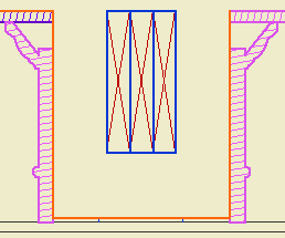
But I don't think we can do it. Certain objects, most prominently Wood Beam JAM9, have clever pen-related section behavior, which the uniform pen feature breaks. This is the wood beam at wall section scale; it knows to draw the X lighter:
But the uniformity heavies up the X along with everything else:
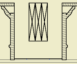
Which is no good, and it really can't be fixed without patches or conversion to drawing, so what's the point. You can always make a line heavier by drawing over it; lighter, not so much.
The technique might be beneficial for interior elevations, since it turns the gray background off. And interior elevations don't show structure members. We should look into it.